Precision Low Frequency Signal Generator Jed Margolin 11/7/2021
The Precision Low Frequency Signal Generator produces a User-selected signal from 10Hz to 90Hz with 0.1Hz resolution for testing subwoofer speakers.
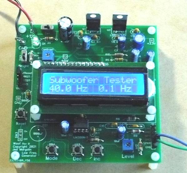
The sine wave is produced by stepping through a table of 64 values and sending them to the MCP4921, a 12-bit serial DAC that uses an SPI interface.
This is how to use the Precision Low Frequency Signal Generator.
INC
- Press and release to increase the frequency
- Press and hold for about 2 seconds to keep increasing the frequency; release to stop
DEC
- Press and release to decrement the frequency
- Press and hold for about 2 seconds to keep decreasing the frequency; release to stop
MODE
- Press and release to toggle the frequency step between 0.1 Hz and 1.0 Hz
- Press and hold for about 2 seconds (then release) to enter Sweep mode at 0.1 Hz increments
- When in Sweep mode Press and hold for about 2 seconds (then release) to exit Sweep mode
The skill level for stuffing the board is: Intermediate. Make sure you use a temperature-controlled soldering iron. I use a temperature of 340 degrees Celsius. And don’t inhale the solder fumes. If you don’t have a fume hood use a fan to blow the solder fumes away from you.
To compile the source code and download it into the microcontrollers I use Texas Instruments Code Composer Studio. It is free and is on this page:
https://www.ti.com/tool/MSP-EXP430G2ET where you can get the versions for Windows, Linux and macOS.
The direct link to the current version for Windows is: https://software-dl.ti.com/ccs/esd/CCSv10/CCS_10_4_0/exports/CCS10.4.0.00006_win64.zip .
The skill level to use Code Composer Studio is: Advanced. (Maybe Really Advanced).
Files
I am providing the following files:
1. Schematic: jm_subwoofer-tester_schematic.pdf
2. Bill of Material: jm_subwoofer-tester_bom.pdf
3. Source Code: (main.c, main.h, and freq64table.h): jm_subwoofer-tester-source.zip
The source code is complete. It does not require any libraries other than the ones that come in Code Composer Studio.
4. Gerber files: jm_subwoofer-tester.zip
You can order blank PC Boards from PCBWAY (they will give me a small royalty):
https://www.pcbway.com/project/shareproject/Precision_Low_Frequency_Signal_Generator.html
Update
In March 2022 I was asked if the frequency range could be extended to test midrange speakers. I went to the spreadsheet I used to create the frequency table and extended it. The new values were too close together to provide the proper 0.1 Hz spacing.
I suggested he use the Tone Burst Generator since it has a mode to produce a continuous tone and can do 1 Hz resolution. I should have checked it first. It did only 10 Hz and 100 Hz resolution. So I added code so that it now does 1 Hz, 10 Hz, and 100 Hz resolution.
Then I tested it with a midrange speaker (a Dual car speaker) and determined that 1 Hz resolution is not good enough.
I went back to this Subwoofer Tester to see what I could do. The problem is that the limiting factor is the time it takes to service an interrupt and the interrupt is what steps the DAC through the sine wave.
So I tried reducing the number of segments for the sine period from 64 to 32. That seems to work but it means the resolution is now 0.2 Hz and 1 Hz.
I tested that with the Dual midrange speaker and I think that is good enough so I am posting it here.
The range is now 20 Hz to 180 Hz with 0.2 Hz and 1 Hz steps. For testing midrange speakers a DVM should be sufficient, you won’t need the Woof Tester.
I considered making one program that could be used either way but that would have made it much more complicated. Besides, if you are going to have boards fabricated you will probably have at least 5 boards made, so stuff two if you need to test both subwoofers and midrange speakers. (There is no change to the hardware.) When I buy parts I buy more than what I need for just one board anyway. Don’t you?
There are some other considerations. The AD9833 that I use in the Tone Burst Generator is a DDS device with a 10-bit DAC and a 28 bit frequency tuning word. When used with a 25 MHz main oscillator (which is the standard speed for the modules) it cannot do good 0.1 Hz spacing at low frequencies.
Analog Devices makes a better DDS device, the AD9850. This also has a 10-bit DAC but it has a 32-bit frequency tuning word. When used with the standard 125 MHz main oscillator I think it would provide good 0.1 Hz resolution even at 10 Hz.
The problem is that the AD9850 module costs a lot more than the AD9833 module. As I write this in March 2022 you can get the AD9833 on eBay for about $4 with about $3.50 shipping. Buy 4 and it comes to about $5 each. The AD9850 costs at least $14 plus about $3.50 shipping. That’s for just one.
A few years ago I used the AD9850 to make my own external VFO for my ancient Ten Tec Omni A (745) ham transceiver which was produced in the late 1970s and early 1980s. The VFO uses a Permeability Tuned Oscillator which means it uses a brass rod going in and out of a coil to vary the inductance to determine the frequency. The problem is that back then the Ten Tec engineers used a lubricant in the coil that hardened over time. If you caught it in time you could use a suitable solvent to dissolve the lubricant and use a more modern lubricant. Unfortunately, if you did not catch it in time the lubricant became indistinguishable from epoxy. That is what happened to mine: Frozen PTO Syndrome. To read about it Click Here.
Notes
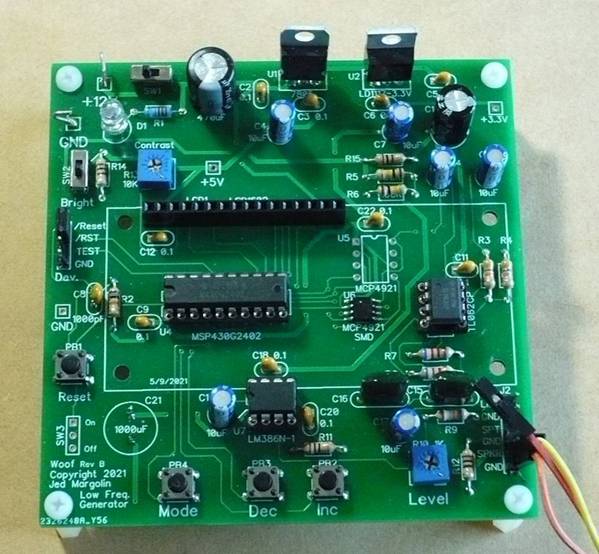
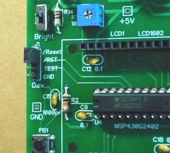
1. Trimpot R13 adjusts the contrast for the LCD Display.
3. The optimum length of the nylon standoffs for the LCD display is 11mm. That is a difficult length to buy. I use 10mm standoffs with a 1mm washer.
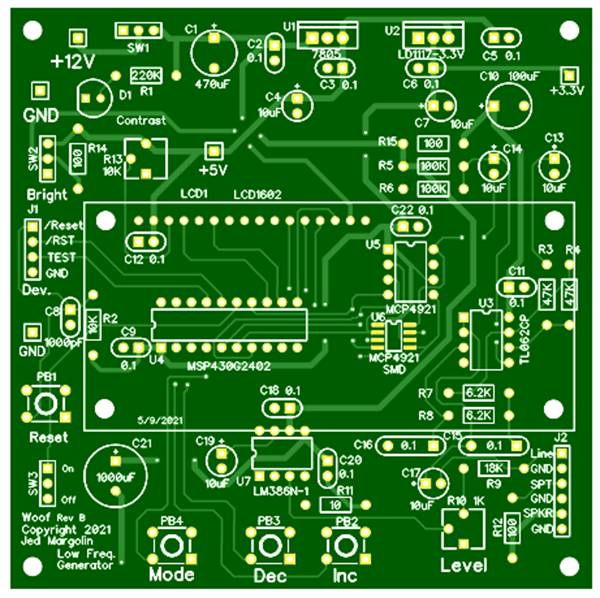
4. This is the bare board top:
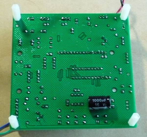
This is the bare board bottom:
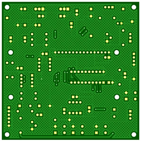
The good ground plane coverage didn’t happen by accident. It certainly didn’t happen by using the auto-router. I placed the parts and routed all of the traces by hand to get good ground plane coverage.
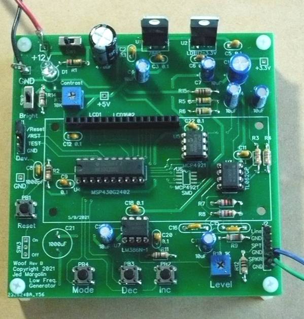
5. To use board space efficiently I put parts under the LCD Display. You can use an MCP4921 in the PDIP package or the SOIC (SMD) version.
6. If you like, you can put C31 on the bottom of the board. That is what I do.
7. I put the DIP ICs in sockets. Always use sockets with machine-tooled pins. The sockets with leaf-springs are crap.
8. When you get the Launchpad, if you want to use it by itself to become familiar with it and Code Composer Studio and you want to use the crystal, you have to jumper the two sets of pads labeled R5 and R7. Here is the MSP-EXP430G2ET User Guide: http://www.ti.com/lit/pdf/slau772.
9. To program the MSG430G2402 you connect the Tone Burst Generator to the Launchpad with three of these wires: Breadboard Jumper Wires 10cm Dupont Wire, Female to Female.
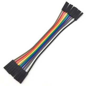
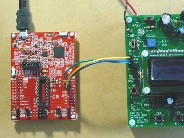
When you use it this way you cannot have a MSP430G2xxx in the Launchpad’s socket. The part is on the Precision Low Frequency Signal Generator Board.
To make it run standalone remove the three wires and use a header plug to connect the /RES and /Reset pins on the header (on the Tone Burst Board).
10. The audio outputs are: Line Level, Speaker, and Speaker Test. The Speaker Test has a 100 Ohm resister in series for testing speakers.
11. The original version could be stuffed either as a Precision Low Frequency Signal Generator or so I could use it with a Bosch BMP-280 temperature and pressure sensor. I live in the mountains 22 miles SE of Reno and my house is at an altitude of about 6,000 feet where the nominal air pressure is 82% of what it is at sea level and I wondered what effect the lower air pressure has on the parameters of a subwoofer speaker. (I did the test in a 55 gallon drum that I pressurized down to sea level.)
12. The board has gone through several revisions since then. I dropped the SPI port for the BMP-280, made the board smaller, changed the voltage regulator from an LM317 to an LD1117-3.3V, and added the pads so I can use the MCP4921 DAC in its PDIP or SOIC package. I think it is ready for Prime Time now.
The testing of subwoofer speakers and the design of subwoofer cabinets is beyond the scope of this article. I recommend the following:
1. For testing subwoofer speakers to derive the Thiele-Small (TS) parameters: Measuring Loudspeaker Parameters by Rod Elliott
Basically, you:
a. Connect the Precision Low Frequency Signal Generator to the subwoofer speaker through the onboard 100 Ohm resistor. This makes the output a current source. You will need a sensitive voltmeter with a good low frequency response or you can use my companion project: Woof Meter which contains a low frequency preamp, a precision full-wave rectifier, and a DC filter. It has a voltage output that can be read with any standard DC meter. It also has a current output for use with an analog 1mA meter. For the Woof Meter project Click Here.
b. Find the free air resonant frequency of the speaker. That is where the voltage across the speaker is at a maximum.
c. Find the higher and lower frequencies where the response is down 3dB. That is 0.707 of the voltage (or current) at resonance.
d. Add a weight of 25 grams to the speaker cone. A U.S. nickel weighs exactly 5.0000 grams so tape 5 nickels onto the cone. (Use masking tape.)
e. Repeat the above tests: find the resonant frequency and the two -3dB frequencies.
f. There are other things for you to measure (with a standard multimeter).
g. Plug your measurements into the proper formulas and you will get the TS parameters. Then you can design the cabinet.
2. For designing subwoofer cabinets for vented, sealed, and custom bandpass cabinets: https://www.ajdesigner.com/speaker/ . Also see: http://www.mh-audio.nl/Loudspeakers.html#top
Happy Subwoofer testing and building.
Jed Margolin
Virginia City Highlands
Storey County
Nevada
11/7/2021 Updated 1/2/2022, 3/13/2022
Postscript (in its original meaning: https://www.dictionary.com/browse/postscript)
This is how I became interested in subwoofers.
1. Several years ago the Storey County (Nevada) Planning Commission was considering an ordinance setting the maximum sound levels allowed for wind turbines. For the proposed ordinance Click Here. It went down only to 20Hz and it specified that it be measured with a meter using A-weighting. I thought the levels were way too loud with A-weighting so I asked the Planning Commission if I could give a demonstration of the sound levels they wanted to allow. They said Ok.
I bought a Polk PSW10 self-powered subwoofer but it is rated only down to 40Hz. So I bought a Sony SA-W3000. It goes down to 20Hz (which is close to what I needed) but could not produce the sound level that I needed to produce. So I decided to build my own subwoofer.
I bought a subwoofer speaker from a well known company and designed and built a ported subwoofer using the company’s speaker parameters posted on their Web site. These are the Thiele-Small (TS) parameters. The subwoofer cabinet that I made had interior dimensions of 18.5” W x 8.4” D x 30.0” H and had a port tuned to 20Hz (I think). When I fired it up it didn’t work anything like it was supposed to. I discovered that the TS parameters on their Web site were different from the ones in the little booklet that came with the speaker. I contacted the company who said that they had closed their U.S. factory and were now having their speakers made in China. And the factory in China might have changed the design so they would try to get the new TS parameters from them. They were successful. The speaker had been redesigned and was now totally different. The TS parameters looked like it had been redesigned to work in a 10” cube. The new TS parameters made it entirely unsuitable for a large subwoofer.
2. I took a chance and bought a subwoofer speaker from a different manufacturer (Alpine) and designed a cabinet with interior dimensions of 25.0” W x 8.5” D x 40.5” H with a port tuned to 16 Hz (I think). It worked ok although you could hear the air rushing in and out of the port at the low frequencies at the maximum sound level. But it would work for the demonstration. I called the Planning Commission office and told the young woman who answered the phone that I had built a subwoofer that would reproduce the sound levels and frequencies that would be allowed by the proposed ordinance, and it would likely rattle the chandeliers in the old Courthouse where the meeting was to be held. Somehow that morphed into that I would break the windows and further damage the Courthouse. My demo was canceled (at 4PM for the 5PM meeting) but because I was on the Agenda I was allowed to speak. I pointed out that the demo would have only reproduced the same frequencies and intensities that they were considering allowing wind turbines to produce. The proposed ordinance was never adopted and, as far as I can tell, was never even on the Agenda again.
3. Even though my demonstration had been canceled and I doubted that I would be allowed to ever give it, the subwoofer took on a life of its own. I built another one. The port had to have a larger throat so there wouldn’t be the port noise that the last one had. I realized that there was no reason why the port has to be inside the cabinet where it takes up volume that had to be compensated for by making the cabinet larger. So I put the port outside the cabinet. For the result Click Here.
It goes down to 12.5Hz at -3dB (measured with a Protek SL1700 Sound Level Meter at 3 feet) and when I tested it inside my house it caused many things in the house to shake. Or maybe it was the house that was shaking. And that was with an amp running at just 30W. The speaker I used (an Alpine SWE-1043) was rated for 250W.
4. The ordinance would have been unnecessary anyway. I blogged the issue of the proposed BLM/Great Basin Wind Energy project which would have put up 69 monster turbines in Storey County, one of which would have 1 mile away from Virginia City and, being on top of the mountain and being 330 feet tall, would have loomed over the city. I also had concerns that the infrasound produced by the monster wind turbines could create a resonance in the old mines under Virginia City and make them collapse. Then it would be Goodbye Virginia City. Fortunately, the project didn’t happen. See http://www.storeycountywindfarms.org/
5. Along the way I wrote two tutorials for the Board of Commissioners:
A Short Course on Sound and Human Hearing.
Click here for html (contains active links to references)
A Short Course on Sound and Human Hearing - Part 2
Click here for html (contains active links to references)
6. I recommend this book: "Wind Turbine Syndrome: A Report on a Natural Experiment," Dr. Nina Pierpont: http://www.windturbinesyndrome.com/
I am not against alternative energy. We absolutely need it. We needed it yesterday.
The problems with wind turbines are:
1. They produce infrasound which travels long distances through the ground and which harms people.
2. The people who make wind farms generally want to connect it to existing transmission lines.
3. The farther away they are from existing transmission lines the more they have to spend to put in their own transmission lines. Therefore, they want to put their wind farms as close as possible to existing transmission lines.
4. Existing transmission lines go to where the demand is, which is generally where people live and work.
If they put their wind farms in cities, lots of people will complain so they want to put them where only a few people live, people whom they assume will not have the political power to keep them out.
Storey County (Nevada) is a small county with a fulltime population of about 3,800 but we have generating plants in the Northern part of the county which supply power to Northern Nevada and parts of Northern California.
The company (Marubeni) wanted to put in their monster wind turbines in the Southern part of the county (where most of us live) and thought we were a bunch of dumb hicks that they could just roll over.
Marubeni was wrong.
.end