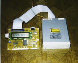
Figure 1
Standalone Controller for an IDE CD-ROM Drive
or
The Secret Life of CDs
by Jed Margolin
Introduction
This project uses a Motorola 68HC908GP20 to control an IDE (ATAPI) CD-ROM
Drive. It also has a 2x20 line LCD Display, six pushbutton switches, an
RS-232 serial interface, a connector for the SPI port, and a header for
emulating 68HC705P6 and 68HC805P18 microcontrollers. The project has two
major operating modes.
Operating Modes
Mode 1:
Mode 1 is a standalone controller for an IDE (ATAPI) CD-ROM Drive for playing audio CDs. The value in this is that if the CD-ROM Drive is able to play CD-RW discs, then it will play audio CDs recorded on CD-RW discs.
CD-RW discs have a lower reflectance value than CD-ROM or CD-R discs and few, if any, consumer CD Players will play them. Most newer CD-ROM Drives do support CD-RW discs.
The other feature of Mode 1 is to display several of the more interesting capabilities of the CD-ROM Drive, namely Manufacturer, Model Number, types of discs it supports (CD-ROM, CD-R, CD-RW), the size of the buffer, the drive's maximum speed, and whether it supports multisession discs.
This is all done without installing the CD-ROM Drive in your computer.
Mode 2:
In Mode 2, the unit connects to a PC Serial Port, and allows the PC to control the system. There are general commands for downloading, uploading, and running code, as well as specialized commands for controlling the CD-ROM Drive and for using the LCD display. The 68HC908GP20's 512 bytes of RAM allows the development of small programs (or functions) which are then added to the main program. (The later stages of the development of this project were done using this method.)
A header for 68HC706P6 and 68HC805P18 microcontrollers allows development for these microcontrollers in a similar fashion.
The connector for the SPI port is for a project that requires streaming
data from a CD-ROM recorded in ISO-9660 form.
Compact Disc Basics
A Compact Disc (CD) contains a single spiral groove more than three miles long made up of pits and lands. In CD-ROMs and commercial Audio CDs the pits and lands are physically stamped into a metal surface (typically aluminum) and then covered by a protective transparent plastic layer. In CD-R and CD-RW discs the pits and lands are produced by using a laser to change the optical characteristics in a dye layer. In CD-R discs this change is permanent. In CD-RW discs the dye can be returned to its "blank" state (erased). A reflecting layer behind the dye layer allows the changes in the dye layer to be read.
The pits and lands do not directly represent the '1's and '0's we are interested in, but must be decoded to produce them. Fortunately, the CD-ROM Drive or CD Player does this. For a discussion of how this is done see the Boden reference [1].
In both Audio and Data CDs the data is organized in blocks of data called sectors that contain 2352 bytes of user data as well as control data called subcode that is put together across several sectors. The subcode is used for addressing the sector and for Error Detection and Correction (EDAC).
In an Audio CD all 2352 bytes of User Data are used for Audio Data. Data CDs come in two flavors: Mode 1 and Mode 2. In Mode 1, the 2352 bytes in the sector are divided into 12 bytes of Sync Data, 4 bytes of Header Data, and 2048 bytes of User Data, with the remaining 288 bytes used for two additional layers of EDAC. In Mode 2, the 2352 bytes are divided into 12 bytes Data, 4 bytes of Header Data, and the remaining 2336 bytes for User Data. Thus, Mode 2 omits the additional EDAC contained in Mode 1. (Has anyone ever seen a Mode 2 disc?)
Normally, in using a Data CD we are only interested in reading the User Data. However, there are special commands for reading the Header and EDAC data. Similarly, in playing Audio CDs we are mostly interested in only playing the audio track. However, once again there are special commands for reading the subcode. Note that in Audio CDs the audio data is not stored sequentially. It is interleaved across several sectors of data in order to make data dropouts (like from scratches) more recoverable.
Now that we have sectors of data on the disc, what do we do with it?
Since Audio CDs came first, we will start with that.
In Audio CDs, the disc is divided into three areas: Lead-In, Program, and Lead Out. Audio selections are assigned to tracks. The address of each track is found in the Table of Contents (TOC) which is stored in the Lead-In area. There are a maximum of 99 tracks. The drive knows where the TOC is and reports the TOC with the READ_TOC command.
The Program area contains the audio tracks. Following the Program area is the Lead-Out area, which is just 90 seconds of silence to let Audio CD players know the music stream has ended.
Now, Data CDs. There are two flavors: Single Session and Multi-Session.
In a Single Session disc there is a single area containing Lead-In, Program, and Lead Out data. Although there is a TOC, there is only one track reported by the READ_TOC command. The location of the track provides the information needed to read the file structure. Actually, in a single-session ISO-9660 disc the location of the information needed to read the file structure is standardized and the TOC is not needed. More on this later.
In Multi-Session discs there are several areas, each containing Lead-In, Program, and Lead Out data. The READ_TOC Command reports the TOC for the last session recorded, which probably explains why multisession discs take longer to become ready. (The drive has to read TOCs until it determines it has found the last one.)
Interfaces
The Compact Disc (audio) was brought out in 1982 by Philips and Sony. (For a history of the Philips effort see reference [2].) Since there was no external interface, manufacturers were free to design the system however they wanted to.
The standard for using Compact Discs for storing digital data came out in 1984 but CD-ROMs did not catch on right away. CD-ROM drives were expensive, as were the CD-ROM products. CD-ROM drive interfaces were either SCSI or proprietary to the manufacturer.
It wasn't until 1993 that a standard using the IDE interface was announced [3]. (The IDE interface was first used in 1986 by Compaq.) The IDE interface is officially known as the ATA (AT Attachment) Interface. The standard for CD-ROM drives is called ATAPI (AT Attachment - Packet Interface).
The IDE Interface is register-based and allows for Direct Memory Access (DMA) for the transfer of data. Data can also be transferred through the registers. This is called Programmed I/O (PIO).
The IDE Interface consists of:
16 bidirectional data lines
3 address lines
2 chip selects (address block select)
lines
as well as several control lines and flag inputs.
The three address lines and two chip selects allow for two address blocks of eight registers.
One chip select is used for an address block of eight registers. The other chip select accesses only two registers; the other six are reserved for a floppy disk controller. The basic operation of the IDE interface can be found in reference [4].
Although both ATA and ATAPI have similar registers, some are used differently, and have been given different names. See Table 1 for ATA register names and Table 2 for ATAPI register names.
One of the challenges in using the IDE bus for CD-ROM drives was to allow two different types of devices, each with its own software driver, to coexist on the same bus. Moreover, it had to work with software already in the field. For example, a command to reset the CD-ROM drive must not also reset the hard drive because the software driver for the hard drive would probably be unaware that its drive had been reset.
The solution was to use an unimplemented ATA command to reset the ATAPI device. Similarly, an ATA reset command is not recognized by an ATAPI device.
At this point you might be wondering why CD-ROMs needed a different interface protocol? Why not just treat it as a read-only hard disk drive?
The answer appears to be the decision to make the interface as much like SCSI as possible in order to preserve the manufacturers' investment in software and firmware.
Yes, the ATAPI standard is modeled after SCSI.
The ATAPI standard is SFF-8020i. You can either buy the final release from ANSI or you can download the pre-release version for free. [5]
SFF-8020i provides all the information needed to control the CD-ROM drive. It provides commands for opening and closing the tray, reading data, and playing audio CDs. There are even commands for telling the CD-ROM to identify itself and its capabilities. This is the reference I used for writing the program.
Data CDs
The primary purpose of this project is to use the an IDE CD-ROM Drive with RW capabilities to read Audio CDs recorded on RW discs. Another purpose is to use a CD-ROM disc to provide streaming digital data for a different project. To do that we will need to discuss how the data is organized on the disc and how files are accessed.
SFF-8020i tells how to control a CD-ROM drive and read the data on it but doesn't say how the data is organized. In other words, how does an an Operating System find and read the files?
When CD-ROM came out, there was no standard. CD-ROMs had to separately come with their own software for reading it. (The programs obviously couldn't be stored on the disc.) In order to bring order out of this chaos, in March 1986 Microsoft hosted a conference to develop a CD-ROM standard for computers. [6]. The standard that came out of this conference was the High Sierra format.
Microsoft developed a software program to integrate High Sierra CD-ROMs into DOS called Microsoft CD Extensions (MSCDEX). High Sierra was submitted to ANSI and a few years later was issued with some minor changes as ISO-9660.
ISO-9660 is probably the most common format for CD-ROMs used today.
A new proposed format is Universal Disk Format (UDF) which makes it easier to record additional files on CD-R and CD-RW discs. [7] As of now the only way to read UDF discs is with a reader program from Adaptec which runs only under W9x. Until UDF is supported either by a DOS program or by everyone's BIOS it can hardly be called "Universal". (How do you install an OS from a UDF disc?)
I chose ISO-9660 for this project because it was the easiest to do.
In an ISO-9660 disc, there is a block of data called the Primary Descriptor Volume which is located in a standard location. This is Logical Block 16 in a single session CD-ROM or Block 16 from the start of each track in a multisession disc. The location of the tracks is produced by reading the Table of Contents with the READ_TOC command as previously discussed. Note that if you know that are reading a single session disc, you don't need to read the TOC. Also note that MSCDEX reads only the last session in a multi-session disc. The previous sessions are still present and readable, but not by MSCDEX.
The Primary Descriptor Volume contains a great deal of information, including the address of the Root Directory.
There are actually two Root Directories. One follows a standard hierarchical structure. The other is a flat structure that contains all of the sub-directory entries (and their sub-directories). The reason for this is to save time looking for a particular file. Seek time in a CD-ROM is slow and the standard was made at a time before there was enough memory (either DRAM or Hard Disk) to devote to storing directory information.
I used three references for deciphering ISO-9660: [1],
[8]
and [9].
Project Development
I started by finding the information on the IDE bus [1], the ATAPI protocol [5], and ISO-9660 [8]. For initial development I used a 486 (running DOS only) and a CD-ROM drive connected to a SoundBlaster IDE port.
By using a DOS-only machine, when my program crashed the system I could quickly and easily reboot without worrying whether I would have to spend the next two days reinstalling the OS. By connecting the CD-ROM drive to the quaternary port (on the SoundBlaster) I did not have to worry about screwing up my hard drive.
I used Borland Turbo C (and its Integrated Development Environment) to develop the program to figure out how ATAPI and ISO-9660 worked.
I used a table-driven menu structure where each table entry contained the label to put on the screen, the location of the label on the screen, and the program function to call when the entry is selected. After the program function is executed it returns to the menu. Additional program functions are added by adding a table entry and writing the program function.
I reached a major milestone when I was able to open and close the tray from the menu. This is not as silly as it sounds because the 'open tray' and 'close tray' commands are sent as ATAPI Command Packets and this meant I was properly sending Command Packets to the drive.
Next I implemented the command to read a data block, specifically the Primary Descriptor Volume. Programming in C made it relatively easy to decode the information and put it on the screen.
Then I used the information in the Primary Descriptor Volume to read the Root Directory and display it on the screen.
Once I was satisfied I was able to access the CD-ROM drive I modified the home-made system I was using as an 68HC05 emulator by adding a port to control a CD-ROM drive.
This emulator contains a 68HC05E0 which is a member of the HC05 series that brings out the memory bus. My system has 8K bytes of external RAM and 32 KBytes of external EPROM. Two of the port lines are dedicated to provide for an RS-232 interface for communicating with a PC.
The monitor program I wrote for it allows me to download, upload, and execute code from a PC.
The 68HC05E0 has been discontinued which is probably just as well, since it uses an interrupt structure that is different from the interrupt structures used by the microcontrollers that I use it to emulate (68HC705K1, 68HC705P6/P9, and 68HC805P18). It also lacks an A/D Converter, which was not a problem until I did a project which used the 68HC705P6's A/D Converter.
I rewrote the C code in 6805 assembly to run in my emulator, and modified my menu program to call it.
Then I did a wire-wrap board with the 68HC908GP20 and got everything to work in it. From that point on I used the 68HC908GP20 for further program development, since the GP20 has 512 bytes of RAM to which I can download code and then execute it. I designed the PC board and FTP'd it to AP Circuits [10]. Their prices for prototype boards are very good. I paid $142 (including shipping) for four boards, each measuring 4.5" x 6.5" . The only downside is that for that price you only get two-layer boards with no silkscreen and no solder mask. But delivery is excellent. I had the boards in my hands 2-3 days after sending the order.
After stuffing a board and verifying that it worked, I put together the final function that called all the functions that had been called separately through my mini-emulator. I programmed a part, and it worked. I retained the capability of using it as a mini-emulator. With a jumper installed in JP4, it will go to the mini-emulator after a Reset. A picture of the board is shown in Figure 1.
Programming the 68HC908GP20
After I had received samples of the GP20, the first order of business was to see if I could program a part. I downloaded the P&E software from the Motorola Web site [11]. The software contained an assembler, simulator, and programmer. This program file (08gpv107.exe) is no longer available. While the original program was able to program blank parts, I was never able to get it to erase a previously programmed part. Fortunately, I found the program GP20Host [12] which, although slow to load and clumsy to use, did let me erase previously programmed parts.
The next version (i8gpz114.exe) worked well, and even let me program previously programmed parts. It, too, has become unavailable. The current version is ICS08GP Version 1.32 [13].
Other useful resources are the GP20 Data Manual [14]
and GP20 Programming Manual [15].
Project Hardware
Figure 2 is a schematic of the project board. Figure 3 is a block diagram of the board. Since the GP20's ports were not sufficient to do everything they have been expanded by the use of U2 (74HC374) and U3 (74HC244).
The 20x2 LCD display (Optrex DMC20261) is run in a write-only mode. This requires that a software timer be used instead of checking the LCD's ready flag. Information for the display is available at the Optrex Web site [16] .
The extra signal in the SPI signal group (FSync) is used to provide a Frame Sync signal so it can talk to the Serial Port of an Analog Devices ADSP2181 Evaluation Board. (This is for another project.)
Project Software
The project software is divided into fifteen areas.
1. Program Initialization.
Initializes the Stack, the PLL, the I/O Ports, and the Serial Port.
2. Program Startup: Looks at the Serial Port Mode Switch and runs either the Standalone CD-ROM Controller (Mode 1) or the Serial Command Program (Mode 2). It then gives the User the opportunity to get the Drive Info before starting the CD Player.
3. CD Player.
4. Serial Port Functions: Send and Receive characters from the Serial Port.
5. Software Timing Functions: Software Wait Functions.
6. Programs for LCD: Power-Reset, write to LCD Instruction and Data
Registers,
write binary characters, convert binary to BCD, and put out messages.
7. Programs for Switches: Read and debounce the switches, and check for positive transitions.
8. Functions for the CDROM Drive.
9. Lower Level CDROM Drive Functions.
10. Functions for ISO-9660 CD Data Discs. (still in development)
11. Various Test Functions for developing software for the CDROM Drive.
12. Serial Mode Program Commands, called from the PC.
13. Interrupt Functions: Read the switches.
14. Vector Redirection Table Functions: All interrupts (except Reset) are redirected to the Vector Indirection Table located in RAM so that programs in Serial Command Mode have access to all processor resources. When executing User Functions downloaded in Serial Command Mode, the program is started from the Reset Vector in the Vector Indirection Table.
These functions are always located at the same fixed memory addresses, and since the code is also fixed, the Security Code Bytes (which are located in the real Vector Table at $FFF6-$FFFD) are always the same. This reduces the chances of losing the Security Code.
15. Jump Table:
A Jump Table (located in gp20jmp.h) contains a table of 'JMP xxxx' instructions so that application programs can access the functions in the main program. Application programs have an include file with labels pointing to the address of the 'JMP xxxx' instruction. Since the Jump Table is at a fixed address, functions in the main program can be moved without affecting application program code.
Typically, after application functions are debugged they are added to
the program with their 'JMP xxxx' instruction added to the Jump Table.
(This method also requires that the application program use the same assignment
for RAM variables.)
Downloadable Software
I am making software for the project available for download under the following terms.
The source code is Copyright 1999, 2001 Jed Margolin (comments@jmargolin.com).
1. Permission is granted to individuals to make copies for their own use.
All other use requires permission of the copyright holder.
2. The author is not held liable for the use of the information contained in the article and accompanying documentation.
3. The article and accompanying documentation may be freely distributed as long as:
a. Jed Margolin is given credit as the author.b. The article and/or accompanying documentation may not be changed in any way without the copyright holder's consent.
c. No money is charged for distributing the article and/or accompanying documentation.
d. All those receiving or distributing the article and/or accompanying documentation agree to be bound by these terms (1 - 3).
If you agree to these terms and wish to download the source code
do
it here.
If not, then don't.
Playing an Audio CD
The block diagram of the program used for playing an Audio CD is shown
in Figure 4. The commands for playing an Audio
CD are found in the SFF-8020i standard [5].
I originally planned to implement the Forward Scan and Reverse Scan commands,
but none of the three CD-ROM drives I tried would recognize these commands.
(I tried a Mitsumi 16X and two Mitsumi 40x drives.)
About the Author
The first computer that I connected my own circuitry to was a PDP8 in the college lab. The PDP8 was one of the original embedded computers, if only because you needed a forklift to move it. The first computer that I actually owned was a KIM-1 with a 6502. It allowed me to develop circuitry for which I received my first patent. I have fourteen patents in fields such as video game technology, graphics memory architecture, aircraft navigation and control, and digital map data compression.
|
|
Copyright 2000, 2001 Jed Margolin