Motorola Flash Innovation 2003
Contest Project Entry F193
NTSC Video Using the
68HC908QY4
Jed
Margolin
Introduction
The
Motorola 68HC908QY4 is used to produce an NTSC video signal which can be
used in several applications. One is an NTSC Test Pattern Generator
which produces simple test patterns in order to evaluate a TV's
geometric distortion, high voltage regulation, and interlace quality.
Another is a VCR Pacifier to allow a VCR to record an audio-only
signal such as from a radio. The VCR Pacifier also includes a real-time
clock which is displayed either in video or by using the TV's closed
captioned decoder. Low-bandwidth data from the 68HC908QY4's A/D inputs
can be displayed the same way, turning the VCR into a two-channel data
logger. As a bonus, a Video Line Trigger is presented which
counts video lines from an external NTSC video source and produces a
pulse to trigger an oscilloscope at the selected line(s).
NTSC Sync
There are
two standards for NTSC video: monochrome and color. The color standard
is compatible with monochrome receivers, but it almost didn't turn out
way. See NTSC Video: Background at the end of this article.
The
monochrome standard calls for a horizontal rate of 15.750 KHz, a
vertical rate of 60.0 Hz, and two interlaced fields of 262.5 lines to
produce 525 lines per frame at 30 Hz.
The color
standard adds a color subcarrier at 3.579545 MHz. and requires that the
horizontal frequency be a ratio of 2/455 times the color subcarrier, for
a frequency of 15.734 KHz. There are still 262.5 lines per field
which gives a vertical frequency of 59.94 Hz. and a frame rate of 29.97
Hz.
The reason
for specifying the horizontal frequency to be such an odd subdivision of
the color frequency is so harmonics of the horizontal frequency do not
interfere with the color subcarrier.
The reason
for having two interlaced fields is to reduce the amount of flicker. It
doesn't eliminate it. Pictures that are bright and contain large solid
areas still flicker. Flicker is also worse if you're tired. (Film, which
has 24 frames/second, flashes each frame twice for an effective
rate of 48 Hz.)
The
following simplified example of a 10-line display shows the difference
between interlaced and progressive scan. (Progressive scan used to be
known as "non-interlaced" until it was pointed out that if you want
people to have a favorable impression about something, tell them what it
is, not what it isn't.)
Interlacing is done by having every other Vertical Blanking Interval
(VBI) start and end 1/2 Horizontal Line early. The Horizontal
trace on a CRT follows the sawtooth pattern shown in the following
figure. Vertical deflection follows a similar pattern but is slower.
Horizontal deflection is not affected by having VBI start and end early.
It just continues on its merry way, so that when it starts the first
line of the second field the vertical deflection has moved it vertically
by 1/2 of a Horizontal line.
The NTSC
standards for Broadcast Television are in FCC Part 73, which is part of
U.S. Code 47 and can be downloaded at : http://www.access.gpo.gov/nara/cfr/waisidx_02/47cfr73_02.html(Scroll
down to FCC 73.699 TV engineering charts and select the PDF version).
Unfortunately,
their conversion of the original document to digital form produced a
very poor result. I found an old paper copy and have scanned it. It's
much more legible. (73.699 File ntscfcc.pdf
).
To simply
things even further I have drawn my own figures (File ntscfigs.pdf ) The timings are specified
referenced to the Horizontal period (H). In the figures I have assumed
the reference of 3.579545 MHz.
Using the 68HC908QY4
Since the
Horizontal rate is defined as 2/455 times the color subcarrier frequency
of 3.579545 MHz. we need to start at twice the color frequency if we are
going to use an integer divider.
Twice the
color frequency is 7.15909 MHz. Since the QY4's bus frequency is clock/4
we need an input clock of 7.15909 * 4 = 28.63636 MHz. (The QY4's maximum
clock is 32 MHz.)
28.63636
MHz. is now a standard crystal frequency and is available from
distributors such as www.digikey.com and www.mouser.com .
The next
step is to figure out how to make each Horizontal line exactly 455 bus
cycles long.
The QY4's
Interrupt Timer can be set to integer numbers of the bus clock, so we
can generate a Timer Interrupt every 455 bus cycles.
However,
when an Interrupt is generated while a multicycle instruction is
executing, the Interrupt is not recognized until the instruction is
finished. This would produce some Horizontal lines with more than 455
cycles.
The only
way to avoid this is to not use multicycle instructions in the Main Loop.
Therefore,
the Main Loop consists solely of NOP instructions (which are single
cycle instructions). All of the real work is done in the Interrupt
functions.
The NOP
Table consists of 455 NOPS followed by a JMP NOP_TABLE. (The JMP is
there as a failsafe, we don't actually want to ever get there.)
When we
return from an Interrupt we will fiddle with the Stack to make the
Interrupt return address the start of the NOP Table.
Finally, to
make things easier, we will use dynamic vector redirection to send the
Timer Interrupt to the proper part of the sync chain. This avoids having
to send the program through a chain of Compares to get where it needs to
be.
There is
still a small problem. The pulses during the Vertical Blanking Interval
(VBI) occur at twice the Horizontal rate. Since the Horizontal period is
455 cycles we cannot divide it exactly in half unless we want to add
hardware. Since the difference is very small (228/227 instead of
227.5/227.5) I chose to not add hardware. TVs and VCRs are very
forgiving when it comes to sync signals; it is much more important that
sync be consistent. So while the QY4 Sync Generator is fine for most
applications, you probably shouldn't use it for running a TV station.
Another
place where my sync deviates from NTSC is in the width of the equalizing
and sync pulses during VBI. Some of the pulses have been widened to
allow the QY4 enough time to handle the overhead required to return from
the Interrupt and respond to the next one. Again, consistency is the
main thing.
By the way,
the purpose of the complicated structure of VBI is to produce an
interlaced display. While much simpler VBI schemes are possible they are
not guaranteed to produce a good interlace. Without the interlace you
would have a picture of 262.5 lines at 60Hz. instead of 525 lines at 30
Hz.
And
finally, line numbers can be confusing. Sometimes line numbers are
referenced to each field so that Field 1 has a line 21 and Field 2 also
has a line 21. It is more useful when line numbers are referenced to the
frame (two fields) so that line 21 is in Field 1 and line 284 is in
Field 2.
The
following is a block diagram of the basic sync program.
Applications
The
Schematics for the following applications are in the file schems.pdf .
The
Programs (including source, listing, and executable for each
application) are in progs.zip .
Standard
NTSC Sync Generator
Hardware:
NTSC Sync Generator
Software: sync.asm
Produces standard NTSC Sync with Composite
Sync, Horizontal Blanking, Vertical Blanking, Color Burst Gate, and
Field Index.
It draws a
square in the center of the screen to show that it’s working.
Here is the
code that does the Horizontal Sync for Field 1 active video.
*===================================================================
* Active Video: Field 1 begins on Line 10, ends on Line 262 1/2
* Real Horizontal Sync
TIRQ3:
* HBLANK signal will be about 11 us total
BCLR
HBLANK,PORTB ; [4]
HBLANK on
* HSYNC front porch (1.27 us = 9 cycles total)
BCLR
HBLANK,PORTB ; [4] waste
cycles
NOP
; [1]
*---------
* HSYNC will be 4.77 us = 34 cycles
BSET
CSYNC,PORTB ; [4]
SYNC on
BCLR
TOF,TSC
; [4] reset interrupt flag
LDX
#8
; [2]
tq3a: DBNZX
tq3a
; [3]
BCLR
CSYNC,PORTB ; [4]
SYNC off
* ---------------------------------------------------
* Color Burst Front Porch Gate 0.38 us (instruction fetch time is
sufficient)
* Color Burst: at least 8 cycles of 3.579545 MHz = 2.3 us = 16
cycles
* We will do 9 cycles of 3.579545 MHz = 18 cycles
BSET
CBGATE,PORTB ; [4]
BSET
CBGATE,PORTB ; [4] waste cycles
BSET
CBGATE,PORTB ; [4] waste cycles
BSET
CBGATE,PORTB ; [4] waste cycles
NOP
; [1]
NOP
; [1]
BCLR
CBGATE,PORTB ; [4]
*---------
* From start of HSYNC to end of HBLANK is 9.22 us = 66 cycles
* We need 6 more cycles
BCLR
CBGATE,PORTB ; [4] waste cycles
NOP
; [1]
NOP
; [1]
BSET
HBLANK,PORTB ; [4]
HBLANK off
*---------
* Check Vertical Count
DBNZ vcount,tq3c
* We have reached the end of active video. Next, start VBI
LDHX
#TIRQ4
; Timer Overflow Vector: Start VBI next time
STHX timer_vec
BSET
VBLANK,PORTB ; oscilloscope
trigger high
JMP TIRQRET
* Video is still active
* We have about 50 us to do something else
tq3c: JSR
Do_Field1
; draw a box
JMP TIRQRET
*===================================================================
Note that it is necessary to count
cycles in many places. The P&E Microcomputer Systems Assembler is
especially nice because it has switches to have the list file show cycle
counts.
The exact string that I use
is: casm08z.exe MYFILE S L D C
S – generate Motorola S19 object file
L – generate LISTING file
D – generate P&E DEBUG file
C – show cycle counts in listing file
In addition, their simulator is
essential when working on a large number of functions that require
counting cycles.
Stripped Down NTSC Sync Generator
Hardware: NTSC Sync Generator
Software: syncn.asm
Produces standard NTSC Sync with
Composite Sync, Vertical Blanking, and Field Index.
This was used in the development of the
other applications. Horizontal Blanking and the Color Burst Gate were
removed in order to free up more QY4 cycles.
Monitor Test Patterns
Hardware: NTSC Monitor Test Pattern
Generator
Software: mtest.asm
 Even after producing all the sync signals
in software the QY4 has time to do other things. This application
produces a few useful test patterns for evaluating a TVs performance to
show problems that are often not apparent when it is displaying a movie
in the store and which become apparent only after you have bought the TV
and used it for a week or two, and which then become increasingly
apparent. And annoying.
Even after producing all the sync signals
in software the QY4 has time to do other things. This application
produces a few useful test patterns for evaluating a TVs performance to
show problems that are often not apparent when it is displaying a movie
in the store and which become apparent only after you have bought the TV
and used it for a week or two, and which then become increasingly
apparent. And annoying.
Warning, these test patterns show a TV's
performance in areas for which there are few, if any, consumer industry
standards other than the manufacturer representative's statement, "Well,
it meets our standards because it looks ok to me."
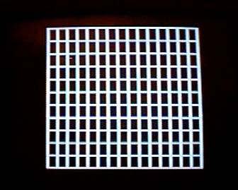
The first pattern is a crosshatch for
evaluating geometric distortion. Geometric distortion causes lines that
should be straight to bend or be outright crooked.
The second pattern is for testing the
TV's High Voltage Regulation. In a CRT the deflection sensitivity is
intimately tied to the high voltage which means that a change in high
voltage changes the size of the picture. If you are watching a TV
program and a change in the brightness of a scene causes the picture
size to change, it can be distracting.

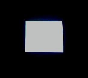
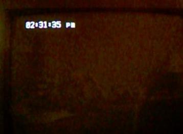
In this test the brightness of a square
having an area of approximately 1/4 of the screen is toggled between 50%
and 100% brightness. (Due to the difficulty getting good pictures from
the screen I used the best picture and changed the brightness in
software.)
It has been my experience that the
larger the TV (CRT) the worse the high voltage regulation, even after
accounting for the larger screen size. In some TVs the high voltage
regulation is so bad that it doesn't hold up even during the period of a
scan line.
The third test shows how well the TV
interlaces the two fields.
The test pattern generator produces two
squares, one during each field, which overlap in the center. (You need a
magnifying glass to properly see the scan lines.)
The screen pictures I took did not
properly show the pattern, probably due to camera speed, so I have drawn
what it looks like. The drawing on the left represents the approximate
size on-screen. The drawing on the right is a closeup of the two
squares. (These drawings assume a perfect interlace.)
This test pattern generator is useful if
you are shopping for a new TV and the salesperson will allow you to
connect it to the store's TVs.
If you are happy with your current TV
you might not want to build it. Once you become aware of a TV's defects
they will become increasingly apparent over time even when watching
regular programming.
VCR Pacifier
A standard consumer VCR has several
features that make it attractive for recording audio-only signals such
as from a radio. A standard T-120 cassette can record 6 hours of
material, the audio quality is pretty good, the VCR has a timer for
starting and stopping recording, and there is a tape counter which, in
modern VCRs, shows elapsed and remaining time. However, in my
necessarily-limited sample of two Toshibas and an RCA, when recording
audio without an accompanying video signal the VCR's tape counter does
not function. (With an earlier generation VCR whose manufacturer I
forget, recording audio without a video signal caused the audio to
warble.)
All we need is a little video to keep
the VCR happy. Since the QY4 can produce NTSTC sync it makes an ideal
VCR Pacifier.
In addition, we are going to add a
real-time clock so we if want to determine the time that a particular
audio segment was recorded we can do so without having to perform clock
arithmetic with the tape counter.
There are two simple ways to record the
clock so it can be played back on any VCR using only a TV. One way is to
use regular video. The other way is to generate a signal that will be
understood by the TV's Closed-Captioned Decoder. (Since 1993 all TVs
having a screen size of at least 13" manufactured for sale in the U.S.
have been required to have a Closed-Captioned Decoder.)
Once we display the clock we will still
have some QY4 processing time (and memory) leftover so we will use the
QY4's A/D inputs to make a simple display for the audio. Since data is
data, we can instead use the method to record and display low-bandwidth
data.
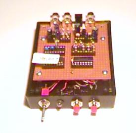
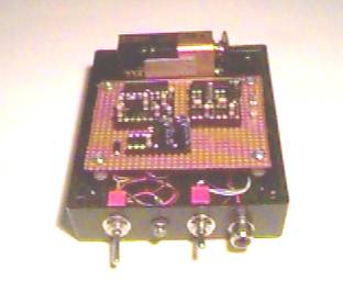
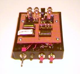
The picture to the right shows the
full-featured VCR Pacifier. The RCA jacks at the rear are for audio/data
input, power, and video output.
The toggle switch at the front is the
power switch. Next to it is the power LED. The two pushbutton switches
are for setting the time. A quick press on the "Increment Time"
Pushbutton increments the time by one minute. Holding it down longer
increments the hours as long as it is held down. The "Decrement Time"
Pushbutton works the same way but decrements the minutes/hours.
The first
step is to do the clock. And first we will do it in video.
VCR
Pacifier - Clock Only, Clock Displayed Using Video
Hardware:
NTSC Video (with Audio Inputs)
Software: clockvid.asm
Programming
a realtime clock would be easy if Vertical Sync was 30.00 Hz.
Unfortunately, it isn't. It's 29.970 Hz. This means that if we just
count Vertical Syncs, at the end of the day (24 hours) instead of
counting 86,400 seconds it will only count 86,312.2 seconds which is
87.8 seconds slow.
Thus, we need to add 87.8 seconds every 24
hours. We could do this by just adding 87.8 seconds at the end of the
day but it will be less noticeable if we spread it out over the entire
day.
The compensation we need is to speed up
the count by a factor of 1.00101691 . We will do this by adding one
count every 984 vertical syncs. (985/984 = 1.00101626). Since we
are counting at the Vertical Sync rate this will be unnoticeable to the
user.
This method can also be used to compensate
for the crystal tolerance in systems where greater time accuracy is
desired. It is cheaper than adding a trimmer capacitor and has the
advantage that it can be made accessible to the user without opening the
case. (It does require a way to access the function, preferably
without adding a switch.)
This
application does not require that kind of accuracy, so we will settle
for adding one count every 984 Vertical Syncs.
Next comes
video, which we will be producing entirely in software.
Since we
will be displaying the clock solely in software the QY4 has to control
the pixels by turning the bits on and off at the proper time.
The normal
method of storing the bit pattern for an alphanumeric character and then
examining it during the scan line to turn the bits on and off would be
too slow.
The method
used is to store the sequence of the actual QY4 instructions and call
the sequence at the proper time.
For example:
Here is the
definition of the number '3' if we used the first approach. The
characters are 8x8 so they require 8 bytes of data.
ch_3:
DC.B $0c,$7e,$3c,$18,$c6,$06,$00,$7c
Here is the definition of the number '3'
using the second approach, showing only the first two lines of the
character:
ch_3:
* $7E
BCLR VIDEO,PORTB
BSET VIDEO,PORTB
BSET VIDEO,PORTB
BSET VIDEO,PORTB
BSET VIDEO,PORTB
BSET VIDEO,PORTB
BSET VIDEO,PORTB
BCLR VIDEO,PORTB
BCLR VIDEO,PORTB
RTS
* $0C
BCLR VIDEO,PORTB
BCLR VIDEO,PORTB
BCLR VIDEO,PORTB
BCLR VIDEO,PORTB
BSET VIDEO,PORTB
BSET VIDEO,PORTB
BCLR VIDEO,PORTB
BCLR VIDEO,PORTB
BCLR VIDEO,PORTB
RTS
Doing it
this way takes a great deal more memory, but the only other option would
be to add hardware or use a faster MCU.
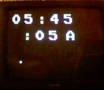
This
picture shows the size of the
characters relative to the size of the TV screen. As you can see, even
with the fast method the characters are very large and you can only fit
6 characters on a line, so it is best viewed on a small TV or a larger
TV a fair distance away. But you can’t beat the price.

VCR
Pacifier - Audio Input, Clock Displayed Using Video
We still
have QY4 cycles and memory leftover so we will connect the audio to one
of the QY4’s A/D inputs and use it to make something on the screen move.
Since the
QY4 A/D inputs are unipolar (0v – VDD) and we are only interested in the
AC component of the audio signal we will capacitively couple it and bias
the A/D input to ½ VDD.
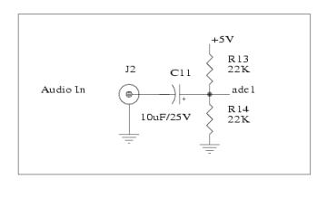 The
audio on adc1 is read on every active video line that is not used for
writing on the screen and each value is compared to the highest and
lowest value already read during that frame. If it’s higher than the
current highest value then it becomes the new highest value. If it’s
lower than the current lowest value then it becomes the new lowest
value.
The
audio on adc1 is read on every active video line that is not used for
writing on the screen and each value is compared to the highest and
lowest value already read during that frame. If it’s higher than the
current highest value then it becomes the new highest value. If it’s
lower than the current lowest value then it becomes the new lowest
value.
The reason
for sampling the audio so frequently (though not on every video line) is
to get a better representation of the audio level than could be gotten
by sampling just once per fame.
Although it
would be nice to be able to display the actual audio waveform, this
would require enough memory to save 16 ms. worth of samples. (This is,
after all, a raster display.)
I came up
with two ways to display the audio signal:
VCR
Pacifier - Audio Input, Clock Displayed Using Video #1
Hardware:
NTSC Video (with Audio Inputs)
Software: audio1v.asm
Realtime Clock, Reads audio from adc1 and displays it as a moving bar in
video.
Audio data is AC coupled,
and is converted to Vp-p during sampling.
Data is sampled several
times per frame (30 Hz).
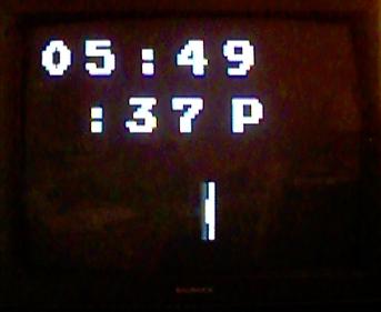
The bars take several seconds to move
from the left to the right. The height of the bar indicates the maximum
amplitude during the frame. Even at a frame period of 16 ms. it’s fast
enough to keep time with speech or music.
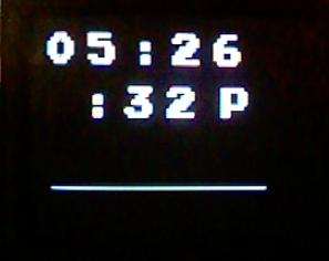
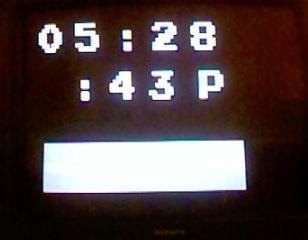
VCR Pacifier - Audio Input, Clock
Displayed Using Video, Audio Display #2
Hardware: NTSC Video (with Audio Inputs)
Software: audio2v.asm
Realtime Clock, Reads audio from adc1 and displays it
as a bar in video.
Audio data is AC coupled, and is converted to Vp-p
during sampling.
Data is sampled several times per frame (30
Hz).
Since data is data,
we can just log the values.
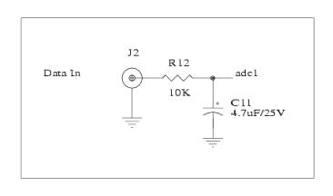
Because the main use
for this application will be for low bandwidth DC data we need a
different circuit for the A/D inputs. The figure at the right is an
example. (It assumes the data is referenced to ground.)
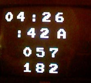
VCR
Pacifier - Data Input, Clock Displayed Using Video
Hardware: NTSC Video (with Data Inputs)
Software: datavid.asm
Realtime Clock, Reads data
from adc0 and adc1 displays the values in video.
Data is sampled once per
frame (30 Hz).
Although the bandwidth is
limited to 15 Hz. It may be useful for low bandwidth
applications like monitoring
temperatures or line voltages.
The number “057” is from adc0; the number “182” is
from adc1. (The values are in BCD).
There is a potential gotcha when using
more than one of the QY4’s A/D inputs because the A/D channels that are
not selected revert to digital port I/O pins.
There will be an obvious problem if the
digital port I/O pin is configured as an output.
However, when configured as an input there is a more subtle problem. If
the input has its pullup enabled it could affect the circuitry that is
expecting to see an A/D input. But if the pullup is not enabled, then
when its A/D input is not selected it will be a digital input that is
either left floating or it will be driven by a signal that could be
somewhere between ‘0’ and ‘1’. Neither is a good idea. (I chose to not
enable pull-ups.)
Closed
Captioning
Now that we have done the VCR Pacifier
(and Data Logger) using direct video for displaying characters we will
do it again using Closed Captioning.
As I mentioned, since 1993 all TVs having a screen size of at least 13"
manufactured for sale in the U.S. have been required to have a Closed
Caption Decoder. TVs with smaller screens are not required to have the
decoder (and I have not seen a small-screen TV that had one.)
The standards for Closed Captioning can be found in 47CFR15.119 which
can be downloaded by going to: http://www.access.gpo.gov/nara/cfr/waisidx_02/47cfr15_02.html
and scrolling down to 15.119 where you can download it in text or
PDF formats.
Both formats leave something to be desired so I have reformatted it to
MS Word to make it easier to read. (File: 47cfr15.doc )
The technical standards for Closed Captioning are in 47CFR73.682 (a)
(22) which can be downloaded by going to http://www.access.gpo.gov/nara/cfr/waisidx_02/47cfr73_02.html
and scrolling down to 73.682 where you can download it in text or
PDF formats.
The section starts with:
(22)(i) Line 21, in each
field, may be used for the transmission of a program-related data signal
which, when decoded, provides a visual depiction of information
simultaneously being presented on the aural channel (captions). Line 21,
field 2 may be used for transmission of a program-related data signal
which, when decoded, identifies a rating level associated with the
current program. Such data signals shall conform to the format described
in figure 17 of Sec. 73.699 of this chapter, and may be transmitted
during all periods of regular operation. On a space available basis,
line 21 field 2 may also be used for text-mode data and extended data
service information.
There is more in the section that you
might find interesting.
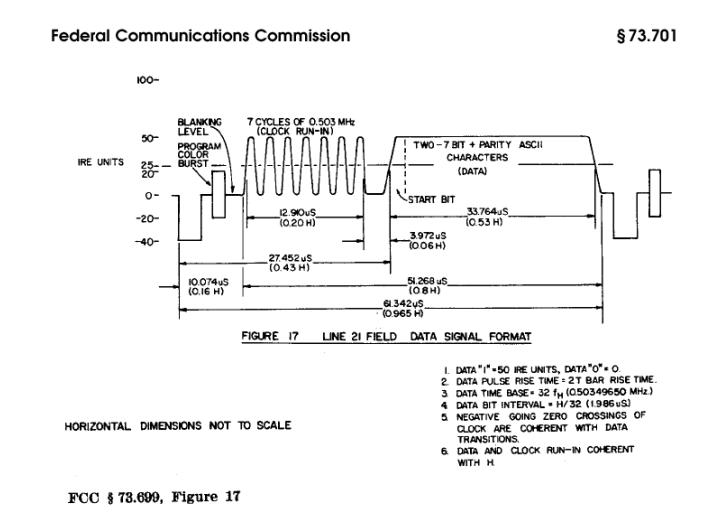
The part that is relevant to us is where it mentions figure 17 of
§73.699. This section was mentioned earlier in this article because
it contains a number of figures for NTSC standards.
You can download the figures by going to: http://www.access.gpo.gov/nara/cfr/waisidx_02/47cfr73_02.html
Scroll down to FCC 73.699 TV engineering charts and select the PDF
version).
Or you can just look at the next figure.
There are some critical items in this
figure that might not be obvious, such as, “What is the Zero-Crossing of
the Run-In Clock?” To show them more clearly I have redrawn part of the
figure.
IRE Units refers to the level of the
signal. 0 IRE Units is the blanking level. 50 IRE Units is half of
maximum brightness. (100 IRE Units would be maximum brightness.)
Notice that Sync is at –40 IRE Units.
The Run-In Clock is specified to go
between 0 and 50 IRE Units so that Zero Crossing refers to where the
zero-value of the sine wave crosses the level of 25 IRE Units.
This is critical because the data bit
transitions are referenced to the zero-crossings of the run-in clock.
If we were generating an actual sine wave we would have to make sure to
use the zero-crossings to clock the data.
However, we won’t be making a sine
wave. We’ll be using a square wave as shown in the next figure. If we
were to use the bottom of the sine wave where it reaches 0 IRE Units as
the zero-crossing we would be off by ¼ bit time and it wouldn’t
work. (I know because that’s what I did the first time.)
My system worked better using 100 IRE
Units for the Closed Captioning signal than with 50 IRE Units, so that’s
what I went with.
You might think that with the low bit
rate (503 KHz.) and with such a robust reference clock a Closed Caption
Decoder would be fairly tolerant of the exact frequency used.
Nope. Look at the FCC’s figure for Note
3 that says, “Data Bit Interval = H/32 (1.986 us), meaning that the
clock is specified as 32H.
I have a Philips Magnavox 25TRC1
that absolutely refuses to recognize a Closed Caption signal unless the
clock is 32H. (Well, ok, the TV was manufactured in November 1994). A
more modern Sharp 13N-M100B, manufactured August 2002, is much more
tolerant (and the picture is excellent, too).
Since we are producing the Closed
Caption bit stream entirely in software we are restricted to clock rates
that can be produced by an integer number of bus cycles (BSET/BCLR
instructions followed by a number of NOPS).
My first effort used the NTSC sync
generator previously described, operating at 28.63636 MHz. to produce
455 bus cycles per Horizontal Line. Although I was able to produce a
Closed Captioning bit clock very close to 503 KHz., it was not at 32H
because 455/32 is not an integer.
Since it worked with the Sharp TV but
not with the Philips Magnavox TV I did not want to make a unit that
would fail to work with the many other older TVs that are undoubtedly
still out there.
Having the unit produce a Closed
Captioning bit stream that ran at 32H and could be produced with an
integer number of bus cycles limits the choices available to around 2.
1. Use a QY4 clock of 32.0 MHz.
with 512 bus cycles per Horizontal line. This produces a sync signal
with a Horizontal frequency of 15.625 KHz. instead of 15.734 KHz.
2. Use a QY4 clock of 32.223 MHz. with 512 bus cycles per
Horizontal line. This produces a sync signal with a Horizontal frequency
of 15.734 KHz.
Unfortunately, while 32.0 MHz. is a
standard frequency for both crystals and oscillator modules, 32.223 MHz.
Is not.
And, although a 32.223 MHz. frequency
could be synthesized it would mean using more hardware.
There is also the issue of the QY4’s
maximum clock speed. The current QY4 data sheet specifies a maximum
clock of 32 MHz. Since other members of the 68HC908 family (like the
68HC908GP32) allow a maximum clock of 32.2 MHz. we could probably get
away with 32.223 MHz. if we promise to use a VCC of 5.0V and not less.
And the winner is:
I built the system using a 32.0 MHz.
clock (and resulting 15.625 KHz. Horizontal sync) and it worked without
any problems on the several TVs and VCRs I have at my disposal.
Now note on the FCC’s figure that
the data consists of two 7-bit characters with parity. In case it’s not
clear from the FCC’s figure, each character has its own parity bit. (And
parity is odd).
The Closed Captioning Taskmaster
There are a number of steps required to
get from knowing the time to sending it out to the TV.
In addition, because the Closed
Captioning protocol only sends out two bytes/frame (and we have 29
frames/second) we can send out only 58 bytes/second. If we want to
update the clock every second (and we do) then we only have 58 bytes to
work with. Since the protocol requires considerable overhead this can be
a real challenge.
In addition, some of the steps require
more QY4 cycles than are available in a Horizontal line, so they are
divided into smaller tasks and spread out over several lines.
We start with a Table (in Flash Memory)
* Requires even
number of bytes
CCMSG:
FDB
PRE+0,PRE+1,PRE+0,PRE+1 ;
repeat commands
FDB PRE+4,PRE+5,PRE+4,PRE+5
FDB
ASCT+0,ASCT+1,COLON
; ASCII Time
FDB ASCT+2,ASCT+3,COLON
FDB ASCT+4,ASCT+5,SPACE,AMPM,AMPM+1,SPACE
FDB POST+0,POST+1,POST+0,POST+1
FDB
$0000
; end of message (for my code)
Each entry points to a memory address
(which may be in Flash or in RAM) which contains data.
The following are commands or
constants so they are in Flash:
PRE:
FCB
$14,$29
; Resume Direct Captioning
FCB
$11,$20
; white (default)
FCB
$11,$40
; white, Row 1
POST:
FCB
$14,$24
; Delete to End of Row
COLON:
FCB $3A
SPACE:
FCB $20
The current time is in RAM. (One
of the steps is to convert the time to ASCII characters because that’s
what is used in Closed Captioning.)
ASCT
RMB 6 ; ASCII Time
Closed Captioning is sent on line 21 of
Field 1 so we have all of Field 2 available to perform some of the tasks.
line 10:
Read and debounce the switches and set the time
line 11: Do the
clock
line 12:
Convert time to ASCII for CC
The
remaining lines are available for putting out video.
In Field 1:
If we are currently sending a CC
Message:
line 10: Get
the next CC data and make odd parity
line 11:
Assemble the CC data into an executable table (part 1)
line 12:
Assemble the CC data into an executable table (part 2)
line 13:
Assemble the CC data into an executable table (part 3)
line 14:
Assemble the CC data into an executable table (part 4)
line 21: Send
out the next CC data pair in the current message
The
remaining lines are available for putting out video.
As in the direct video character
generator discussed previously, the QY4 is not fast enough to assemble
the required bitstream while it is sending it. However, while the
bitstream for the video character generator can be stored in Flash, the
CC data is too dynamic and must be stored in RAM. Fortunately, we are
only sending two bytes of data per frame and there is just enough RAM to
do it.
So, at line 21, after sending the run-in
clock and waiting during the 2-bit wait time, we JSR to the sequence of
instructions (BSETs, BCLRs, and NOPs) dynamically assembled and placed
in RAM.
Note that because we can only update the
Closed Captioning display once per second, those applications that also
display data also can only update the data displayed in Closed
Captioning once per second.
However, those applications that display
the data in direct video as well as in Closed Captioning can update the
direct video display every frame.
In addition to the FCC document for
Closed Captioning (File: 47cfr15.doc
), another very useful reference is Video Demystified by Keith
Jack, LHH Technology Publishing, 2001. In addition to explaining
Closed Captioning (which is sent on Field 1 line 21) it explains what’s
on Field 2 line 21 (otherwise known as line 284).
To avoid leaving you in suspenders, I’ll
give you a hint. Line 284 is for Extended Data Services and contains
things like program rating, program name, program type, and a bunch of
really interesting information that TVs and VCRs don’t display. (At
least, mine don’t.)
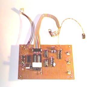
The picture at the right shows the
hardware for the VCR Pacifiers using Closed Captioning. It’s actually
the same box used for the VCR Pacifiers using Direct Video. It was wired
to accept either the 28.63636 MHz. crystal (and associated components)
or the 32 MHz. oscillator module.
VCR Pacifier - Clock Only, Clock
Displayed Using Closed Captioning
Hardware: Closed Captioned Video (with
Audio Inputs)
Software: clockcc.asm
Because the sync is slower than NTSC we need to revisit the realtime
clock. Since our VSync is slower (29.762 Hz. Instead of 29.970 Hz. for
standard NTSC) we would be 685.7 seconds short after 24 hours.
We will fix it by adding a count every
126 counts.
VCR Pacifier - Audio Input, Clock
Displayed Using Closed Captioning, Audio Display #1
Hardware: Closed Captioned Video (with
Audio Inputs)
Software: audio1cc.asm
Realtime Clock, Reads audio
from adc0 and adc1 and displays it in BCD in Closed Caption and as
moving bars in video.
Audio data is AC coupled, and is converted to Vp-p during
sampling.
Data is sampled several times per
frame (30 Hz).
Closed Caption is updated once per
second. Audio bars are updated every frame.
The bars take several seconds to move
from the left to the right. The height of the bar indicates the maximum
amplitude during the frame. Even at a frame period of 16 ms. it’s fast
enough to keep time with speech or music.
VCR Pacifier - Audio Input, Clock
Displayed Using Closed Captioning, Audio Display #2
Hardware: Closed Captioned Video (with
Audio Inputs)
Software: audio2cc.asm
Realtime Clock, Reads audio from adc0 and adc1 and
displays them in BCD in
Closed
Captioned and as bars in video.
Audio data is AC coupled, and is converted to Vp-p
during sampling.
Data is sampled several times per frame (30 Hz).
Closed Caption is updated once per
second. Audio bars are updated every frame.
The audio in the picture at the right
was louder than in the picture at the left.
VCR Pacifier - Data Input, Clock
Displayed Using Closed Captioning, Data Display #1
Hardware: Closed Captioned Video (with Data Inputs)
Software: data1cc.asm
Realtime Clock, Reads data from adc0 and adc1 and
displays it in BCD in
Closed Caption and as moving bars in
video.
Data is DC
coupled, and is averaged during sampling.
Data is sampled
several times per frame (30 Hz).
Closed Caption is updated once per second. Data bars are updated every
frame.
(Since the display looks the same as the
configuration for audio, I have used the same pictures.)
VCR Pacifier - Data Input, Clock
Displayed Using Closed Captioning, Data Display #2
Hardware:
Closed Captioned Video (with Data Inputs)
Software: data1cc.asm
Realtime Clock, Reads data from adc0 and adc1 and displays it in BCD in
Closed Caption and as bars in video.
Data is DC coupled, and is averaged during sampling.
Data is sampled
several times per frame (30 Hz).
Closed Caption is updated once per
second. Data bars are updated every frame.
(Since the display looks the same as
the configuration for audio, I have used the same pictures.)
Software Development
Software development was done using the
free assembler and simulator software from P&E Microcomputer Systems
(www.pemicro.com).
As previously noted, it is necessary to
count cycles in many places. The P&E Microcomputer Systems Assembler
is especially nice because it has switches to have the list file show
cycle counts.
The exact string that I use
is: casm08z.exe MYFILE S L D C
S – generate Motorola S19 object file
L – generate LISTING file
D – generate P&E DEBUG file
C – show cycle counts in listing file
In addition, their simulator is
essential when working on a large number of functions that require
counting cycles.
Hardware Development
I made my own simple hardware
development system.
The schematics are included in the
schematic package (Programmer for 68HC980QY4 in schems.pdf
).
In addition to programming the QY4 there
is a header for connecting it to the project being developed.
The toggle switch at the upper right
turns power on and off (SW1).
The toggle switch at the lower right
(SW2) switches between Programming and Development Modes.
In Programming Mode the QY4 receives a
clock of 19.6608 MHz. which produces a Serial I/O speed of 19.2 Kbaud.
SW2 also puts the QY4 into Monitor Mode after a Power-On Reset.
In Programming Mode PTA0 and PTA1 are
connected as required for programming. PTA0 is used for serial
communications, PTA1 is required to be high during Power-On Reset. After
the QY4 has gotten into Monitor Mode PTA1 can be used by the target
using the toggle switch at the middle right side (SW3). This feature is
to allow you to use the P&E Debugger and did not prove to be
especially useful for this project because Debug Mode must be run using
the 19.6608 MHz. clock. Mostly it was a nuisance because if it is in the
wrong position (Development instead of Programming) PTA1 is connected to
the target and if PTA1 is not high the QY4 does not go into Monitor
Mode.
When SW2 is in Development Mode, the QY4
receives the clock required by the target circuit, PTA0 and PTA1 are
connected to the target board, and the QY4 comes up in User Mode.
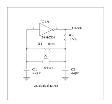
The original NTSC application required a
clock of 28.63636 MHz. and used a crystal for that purpose in the
standard CMOS crystal oscillator circuit shown to the right. (At this
frequency R2 is not needed.)
However, the applications using Closed
Captioning required 32 MHz. By then, I had already built the board and
did not have space to add a 32 MHz. oscillator module close to the QY4.
When I used a 32 MHz. crystal in place
of the 28.63636 MHz. crystal the circuit refused to oscillate at 32 MHz.
The frequency was much lower, more like 10 MHz.
Here’s why.
Crystals are made of a piezoelectric
material like quartz. Applying a mechanical force to the material
produces an electric field, and applying an electric field to it causes
it to mechanically distort.
Mechanical resonances in the material
create electrical resonances. That’s why they are used as more or less
stable frequency determining elements. (We will not go into parallel
versus series resonance.)
The resonant frequency of a crystal is
determined by its physical dimensions, in particular its thickness.
However, starting at about 30 MHz. the crystal would be too thin, and
thus, fragile.
As a result, crystal manufacturers
optimize the crystal’s shape to produce harmonics (called overtones) of
the main resonant frequency. Crystals up to 30 MHz. are generally
fundamental-mode devices.
Starting at about 30 MHz. they are
optimized for third harmonic operation. At VHF frequencies they may be
designed for fifth overtone operation.
What this means is that a 32 MHz.
crystal has a fundamental mode frequency of about 10.6 MHz. and if you
use it in a circuit like the standard CMOS circuit show above, it will
oscillate at 10.6 MHz. just like mine did.
In order to get it to oscillate at its
third overtone frequency (32 MHz.) we have to add some components.
Oscillator design is more an art
than a science but the following circuit did the trick.
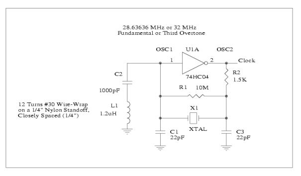
Inductor L1
forms a parallel resonant circuit with capacitor C1 at about 30 MHz.
Capacitor C2 is a DC blocking capacitor. Resistor R2 is no longer
optional.
The 30 MHz. resonant circuit presents
a high impedance at 30 MHz. and a low impedance at other frequencies
(higher or lower), like 10 MHz.
As a result, the feedback to the input
of U1A is frequency dependant and is the greatest at about 30 MHz.
Therefore the circuit oscillates at the crystal overtone at 32MHz. and
not the fundamental at 10.6 MHz.
This circuit also works connected directly to the QY4 by omitting U1A
and connecting OSC1 and OSC2 to the corresponding QY4 pins. (The QY4 has
a CMOS inverter connected between its OSC1 and OSC2 pins.)
With the circuit as shown in the
schematics I can install either a 28.63636 MHz. or 32 MHz. crystal and
it just works. (Note that I made L1 myself. It’s easy, try it.)
Bonus - Video Line Trigger
In trying to
figure out how to generate a Closed Captioning signal I looked at the
Closed Captioning signal produced from a variety of sources: DVD Player,
VCR, C-Band Satellite (analog), and Over-The-Air TV.
While my trusty Tektronix 2215
oscilloscope has a TV Sync Trigger, the trace is very dim when viewing
signals that occur only once every 16 ms. And, while my Tektronix 2445
produces a brighter trace it lacks a TV Sync Trigger.
I have an unrelated project that uses a
National LM1881 sync separator IC. Not only does the IC produce
Composite Sync and Vertical Sync, it also outputs an Odd/Even Field
signal. All I had to do was fire up the board and attach the ‘scope to
get a nice Frame Sync trigger.
Since I had lots of unused space on the
prototype board I added a QY4 to count VSyncs and produce a trigger
signal at line 21.
I also wanted to look at line 284 so I
added another output that goes high during line 284 and connected it to
the ‘scope’s Channel 2. (The Video is connected to Channel 1.) Then I
set the ‘scope to add Channel 1 and Channel 2. (The Trigger Output is
connected to the ‘scope’s external trigger input.)
The result is to provide an offset
voltage to separate the line 21 and line 284 traces.
Then I thought it would be nice to be
able to select other lines to look at.
Since I had already used the QY4 as a
simple character generator I decided to use it to display the lines
selected by pushbuttons.
Using a single QY4 to count the lines
from the video signal and to produce the on-screen display would have
required that the QY4 be synchronized to the video signal. While that is
certainly possible, it was cheaper and easier to just add another QY4.
To make it even easier, I ran both QY4s
from the same 32 MHz. oscillator module. (Dividing it into 508 cycles
per Horizontal line produces a Horizontal Sync of 15.748 KHz. which is
between color sync and monochrome sync.)
The circuit is part of the schematic
package (File: schems.pdf ) and the software
for both QY4s is in the Software package (File: progs.zip).
In the following picture, the parts
inside the areas outlined in red are the ones used in this application.
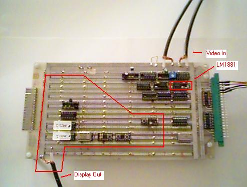
The first QY4 (MCU1) keeps track of the lines from the Video Source and
produces outputs at the selected line(s) as described above. The second
QY4 (MCU2) reads the switches to select the lines(s), sends the line
selection to MCU using a simple synchronous serial protocol, and
produces the video display showing the line(s) selected.
Because
not everyone has a two-channel ‘scope with the ability to add the
channels together I put in a jumper header, connected to both MCUs, to
tell them whether to do two lines or just one.
The default for MCU1 is to look at
lines 21 and 284 (or just line 21). If you just want to look at these
lines you can leave out MCU2. In that case, since you also won’t need
the video output circuitry, make sure you ground the inputs to U3A, U3B,
and U3C so they are not left floating.
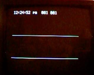
This is the display of the dual channel
mode. Switches SW4 and SW5 increment/decrement the line number of
Trigger #1.
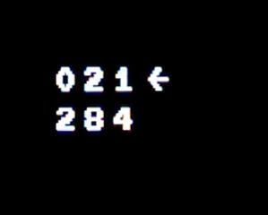
After pressing switch SW3, switches SW4
and SW5 will increment/decrement the line number of Trigger #2.

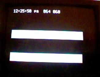
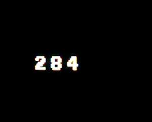
This is the display of the single channel
mode. Switches SW4 and SW5 increment/decrement the line number of the
trigger.
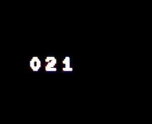
After pressing switch SW3 the trigger
changes to line 284, which is Field 2 line 21.
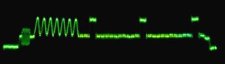
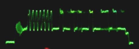
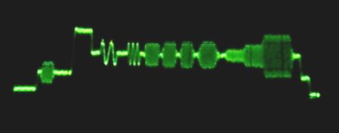
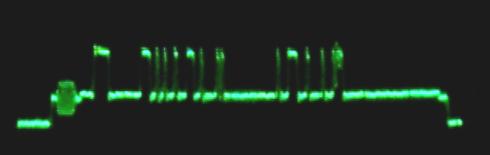
The following pictures were taken using a
Tektronix 2445 Oscilloscope. The various devices were connected to the
Video Line Trigger through 20’ of RG-59 coax. Notice that some signals
are cleaner than others. Also note that the Closed Captioning signal on
the VCR starts and ends later than the others, although once it starts,
it does follow the Closed Captioning specification.
What is not
apparent from the pictures is that with signals that are Macrovision
encoded, the Video Line Trigger line numbers are wrong due to the extra
sync pulses inserted into the Vertical Blanking Interval by the
Macrovision process.
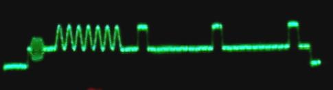
Toshiba SD-2700 DVD player, playing
“Groundhog Day” (1993).
DVD sending ‘zeros’:
The first bit after the run-in
clock is the Start Bit. Then it sends seven ‘zeros’ and a parity bit.
Since it uses odd parity the parity bit is a ‘one’. Then it sends seven
more ‘zeros’ and a parity bit.
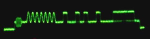
DVD sending data:
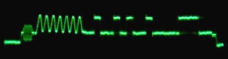
This shows the timing between the
last zero-crossing of the run-in clock and the start bit.
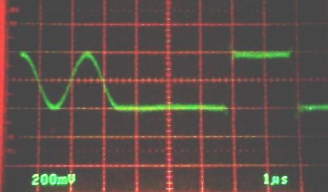
Toshiba M-775 VCR playing Wallace and
Gromit: The Wrong Trousers (1993).
Notice the funky color burst. Possibly the VCR did not like driving the
20’ of RG59U I was using. (Although the DVD didn’t seem to mind.)
VCR sending data:
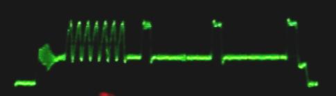
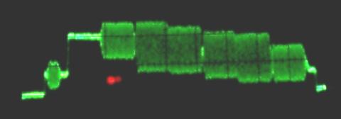
C-Band Satellite (Analog) using a
Uniden Supra receiver. The
program was on the PBS transponder. Notice how clean the signal
is.
Sending data:
Another transponder signal: Line
38 – one line of a color bar test pattern:
Test Signal, Line 16:
Line 14 – another data stream:
Here it is in two-channel mode
showing a bitstream on line 18 and the Closed Captioning signal on line
21.
The Video Line Trigger was a quick project to allow me to see line 21
in order to get my own Closed Captioning software to work. There are
some things that it does not do:
1. It cannot be set
to lines within the Field 1 Vertical Banking Interval.
2. In two-channel
mode it cannot be set to consecutive lines.
3. It does not detect
Macrovision-encoded video and correct for the extra sync pulses that
Macrovision inserts during the Vertical Banking Interval.
The Video Line Trigger is useful for
selecting and examining video lines using oscilloscopes that do not have
a TV Sync feature.
It is also useful with inexpensive
oscilloscopes that do not have a dual time base.
Even with oscilloscopes with a dual time
base, it allows you to examine selected lines without having to count
sync pulses.
NTSC Video: Background
The National Television Service
Committee (NTSC) was a committee set up in 1936 by the Radio
Manufacturers Association (RMA), now the Electronic Industries
Association (EIA), to recommend to the FCC the standards for commercial
television broadcasting service in the United States.
The first standards (for monochrome)
were adapted in June 1941. However, the development of television
broadcasting was soon interrupted by the United States' entry into the
Second World War and did not resume until the end of the War in 1945.
The monochrome standard calls for a
horizontal rate of 15.750 KHz, a vertical rate of 60.0 Hz, and two
interlaced fields of 262.5 lines to produce 512 lines per frame at 30
Hz.
The reason for choosing 60.0 Hz for the
vertical rate was because 60.0 Hz is the power line frequency in the
United States. Since the transistor would not be invented until
1947 (and it would be several more years before it would be improved
enough to use in TVs), electronics meant vacuum tubes which required
operating voltages of several hundred volts (more or less). Power
supplies used passive filters with capacitors and, sometimes, also
inductors. (Vacuum tubes were too expensive to be used as voltage
regulators.)
As a result, there was a significant
amount of power supply ripple present compared to the level of the video
signal and it was difficult to keep the power supply ripple out of the
video. The effect on the display is to produce hum bars.
Although making the frequency for the
vertical rate the same as the power mains would not reduce the hum bars,
at least they would be stationary and not constantly moving through the
picture which would make them even more noticeable. (In Europe,
where the power line frequency is 50.0 Hz, they used a vertical
frequency of 50.0 Hz.)
The standards for color were adopted in
December 1953 after several years of wrangling and jockeying for
position by the companies having a stake in the outcome. The FCC
originally adopted the field-sequential method proposed by CBS which
used a rotating color wheel and was incompatible with the existing
monochrome standard. The method proposed by RCA was compatible with
existing receivers but produced extremely poor pictures. It used a
pixel-sequential method that was beyond what the technology of the time
was capable of reliably supporting. The system that ultimately emerged
was the result of the contributions of several companies, notably
Hazeltine, General Electric, and Philco.
The NTSC color standard makes use of the
fact that the human eye has a lower bandwidth for color than it has for
grayscale details.
The grayscale values of the color
picture are sent in baseband video at relatively high bandwidth. The
color information is sent on a color subcarrier at a much lower
bandwidth. (Technically, what is sent is a pair of two color difference
signals in quadrature.)
Monochrome receivers don't see the color
subcarrier and simply display the grayscale picture.
The color standard calls for the color
subcarrier to be 3.579545 MHz. and requires that the horizontal
frequency be a ratio of 2/455 times the color subcarrier, for a
frequency of 15.734 KHz. There are still 262.5 lines per field which
gives a vertical frequency of 59.94 Hz. and a frame rate of 29.97 Hz.
The reason for specifying the horizontal
frequency to be such an odd subdivision of the color frequency is so
harmonics of the horizontal frequency do not interfere with the color
subcarrier.
Scaling everything up from 60.0Hz (with
a 15.750 KHz horizontal frequency) would have required a color
subcarrier of 3.583125 MHz. Presumably, there were good technical
reasons for not doing this. Perhaps scaling everything up from 60.0Hz
would have made the video bandwidth interfere with the existing TV sound
carrier at 4.5 MHz. or maybe the 4.5 MHz. sound would have interfered
with the color subcarrier.
Links
Motorola: 68HC908QY4 Product Summary
Page: http://e-www.motorola.com/
Use Search and type: 68HC908QY4 Product Summary
Then select the 68HC908QY4 Product Summary Page.
P&E Microcomputer Systems: www.pemicro.com
General Distributors: www.digikey.com www.mouser.com
FCC: Part 73.699 Figures - NTSC
standards for Broadcast Television
www.access.gpo.gov/nara/cfr/waisidx_02/47cfr73_02.html
(Scroll down to FCC 73.699 TV engineering charts and select the PDF
version).
Part 15.119 - FCC Protocol for Closed
Captioning
www.access.gpo.gov/nara/cfr/waisidx_02/47cfr15_02.html
(Scroll down to FCC 15.119 )
Part 73.682 (a) (22) - FCC technical
standards for Closed Captioning
www.access.gpo.gov/nara/cfr/waisidx_02/47cfr73_02.html
(Scroll down to FCC 73.682)
Files: FCC Part 73.699 NTSC
Figures:
ntscfcc.pdf
FCC Part 73.699 NTSC Figures
Redrawn: ntscfigs.pdf
FCC Part 15.119 Protocol Standards for
Closed Captioning: 47cfr15.doc
Schematics for
Applications: schems.pdf
Software for
Applications: progs.zip
NTSC Web site: http://ntsc-tv.com/ntsc-index-01.htm
A web site for the history of early
color television by Edwin Howard Reitan, Jr.:
www.novia.net/~ereitan/
More television links: http://history.acusd.edu/gen/recording/television0.html
Recommended References:
Video Display Engineering by Jerry
Whitaker, McGraw-Hill, 2001.
Video Demystified by Keith Jack,
LHH Technology Publishing, 2001.
Jed Margolin
San Jose, CA
September 30, 2003