PLASMA LASER AMPLIFIER
JED MARGOLIN
November 11, 2016
BACKGROUND OF THE INVENTION - Field of Invention
[001] This invention relates to the field of lasers and laser amplifiers.
An ultrafast laser is a laser that produces pulses in the femosecond to picosecond range. Lasers producing longer pulses may also be used.
A wiggler is a device that produces alternating magnetic fields. The terms wiggler, undulator, and wobbler shall mean the same thing.
A plasma is a collection of atoms that have absorbed sufficient energy that their electrons have been stripped away, leaving only their nuclei.
BACKGROUND OF THE INVENTION – Prior Art
[002] One of the first practical ultrafast lasers is taught by U.S. Patent 5,726,855 Apparatus and method for enabling the creation of multiple extended conduction paths in the atmosphere issued March 10, 1998 to Mourou, Braun, Diels, Bouvier, and Zhau. {Ref. 1}
The use of a wiggler in a free-electron laser is taught by U.S. Patent 3,822,410 Stimulated emission of radiation in periodically deflected electron beam issued July 2, 1974 to Madey. It uses an intricate structure of electromagnets and iron cores. {Ref. 2}
An early reference on plasma wigglers is Wave Wigglers for Free Electron Lasers by Joshi, Dawson, Yan, and Chen (1987). {Ref. 6}
OBJECTIVES AND ADVANTAGES
[003] The wigglers used so far have used mechanical arrangements of various types of magnets to produce the alternating magnetic fields that constitute a wiggler. Because they are mechanical the distance between the alternating magnetic fields must be of at least a certain distance in order to be physically realizable. The objective of the present invention is to use the beam of an ultrafast laser in a tube filled with gas so the very short pulse of the laser ionizes the gas producing a wiggler.
SUMMARY OF THE INVENTION
[004] The beam of an ultrafast laser is introduced in a tube filled with gas so the very short pulse of the laser ionizes the gas producing a strong magnetic field at the leading edge of the pulse and another strong magnetic field of opposite direction at the trailing edge of the pulse. This produces a simple wiggler where the distance between the alternating magnetic poles is extremely short. The ionized beam produced by the laser conducts electricity so the driving energy is just a DC power supply. The extremely short distance between the alternating magnetic poles of the wiggler allows the coherent radiation produced by the wiggler to have a very short wavelength without using the extremely high voltages required by a standard free-electron laser.
[005] In a first preferred embodiment the beam from an ultrafast laser is introduced into a gas filled cylinder through a window that is transparent to the wavelength of the ultrafast laser. A reflecting mirror that conducts electricity reflects the beam longitudinally through the cylinder. At the end of the cylinder is another reflecting mirror that conducts electricity. The extremely short pulse from the ultrafast laser produces a wiggler in the gas which, because of the power of the ultrafast laser, becomes ionized (i.e. a plasma) in and around the beam and which then conducts electricity. A DC power supply connected between the two reflecting mirrors produces a current in the wiggler plasma. The wiggler converts this current into coherent radiation which is reflected by the reflecting mirror at the end of the cylinder and exits the cylinder through the transparent window at the end of the cylinder. The reflecting mirrors can be made from beryllium {Ref. 8}.
The cylinder is preferably made of a non-conducting material such as glass or ceramic. The gas in the cylinder is a gas that can be ionized by the ultrafast laser. Suitable gases that can be easily ionized include neon, hydrogen, and even the low pressure mercury used in common fluorescent bulbs. The term cylinder is used for convenience. The cylinder does not have to actually be a cylinder. It is any long tube with a suitable cross section. The cross section can be square, rectangular, triangular or almost any shape.
[006] In a second preferred embodiment two plasma laser sections are cascaded. Each one has its own DC power supply and the two gas filled cylinders share the same gas. This results in the two DC power supplies being connected in series which could cause insulation breakdown if the DC power supplies produce a high voltage. This is not a problem for relatively low voltages. More than two plasma laser sections can be cascaded as long the insulation of the DC power supplies does not break down under the voltages used.
[007] In a third preferred embodiment two plasma laser sections are cascaded but the two sections are electrically isolated by a vacuum cylinder so the DC power supplies can have a common ground. This prevents the possibility of insulation breakdown from having two high voltage DC power supplies connected in series. Using two power supplies makes it possible to use two different voltages. This makes it possible to tune the wavelengths of the two plasma laser sections for phase locking or other purposes. Because the two gas filled cylinders are completely independent the two gas filled cylinders can even use different gasses. For some applications the two plasma laser sections can use the same DC power supply.
[008] In a fourth preferred embodiment the output laser beam is electrically charged to provide increased lethality when it is used as a weapon. This is possible because the output of the plasma laser amplifier will also be an ultrafast laser beam. A vacuum cylinder provides the desired amount of electrical isolation between the DC power supply used in the plasma laser amplifier and the DC power supply used to charge the output beam. As an alternative the output beam can be charged with an AC current. The output beam from two or more cascaded plasma laser amplifiers may be charged using this same method.
If the electrical isolation provided by transparent window at the end of the gas filled cylinder is sufficient and no further isolation is necessary then the vacuum cylinder can be omitted.
[009] The gas in the gas filled cylinders can be heated by a separate source in order to reduce the amount of power required from the ultrafast laser. For example, heating the gas to 50% of its ionization threshold should reduce the amount of power required from the ultrafast laser by 50%. The heating of the gas can be done with a simple electric resistance heater, a microwave source, or a continuous wave (CW) laser.
[010] One of the proposed uses for the ultrafast laser taught by the Mourou patent (5,726,855) is to discharge clouds to protect high value assets from lightning strikes (Column 2 lines 13-23, and Figure 3). This might not be a good idea since the wiggler created by the ultrafast laser is likely to convert the energy of the cloud (at nearly the energy of a lightning strike) into x-rays.
BRIEF DESCRIPTION OF THE DRAWINGS
[011] Figure 1a is a general illustration showing the cross section of a laser beam.
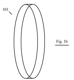
[012] Figure 1b is a general illustration showing that the shortness of the laser pulse produces a very thin disk.
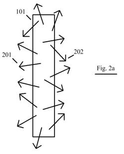
[013] Figure 2a is a general illustration showing the natural tendency of the electrons being stripped from the gas atoms in the disk to scatter in all directions.
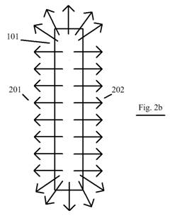
[014] Figure 2b is a general illustration showing that Coulomb repulsion causes the electrons to distribute themselves uniformly around the disk.
[015] Figure 3a is a general illustration showing the circular magnetic field produced by a single electron trajectory using the Right Hand Rule. The electron flow is into the paper.
[016] Figure 3b is a general illustration showing the circular magnetic fields produced by two parallel electron trajectories.
[017] Figure 3c is a general illustration showing that the circular magnetic fields produced by two parallel electron trajectories combine into a larger circular magnetic field.
[018] Figure 3d is a general illustration showing that the circular magnetic fields produced by a number of parallel electron trajectories combine into a larger circular magnetic field.
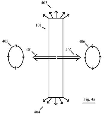
[019] Figure 4a is a general illustration showing the magnetic fields produced by a short laser pulse creating a plasma from a gas.
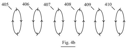
[020] Figure 4b is a general illustration showing the alternating magnetic fields produced by a short laser pulse as it travels through a gas, creating a plasma wiggler.
[021] Figure 5a is a general illustration showing the first embodiment of the plasma laser amplifier with the power supply grounded at the negative terminal of the power supply.
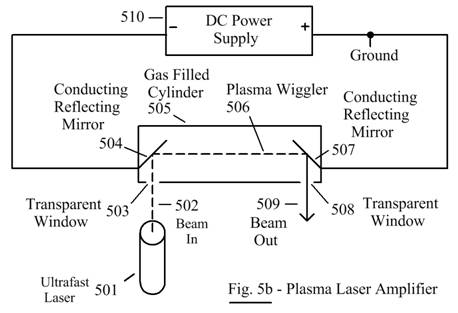
[022] Figure 5b is a general illustration showing the first embodiment of the plasma laser amplifier with the power supply grounded at the positive terminal of the power supply.
[023] Figure 6 is a general illustration showing the second embodiment which cascades two plasma laser amplifiers.
[024] Figure 7 is a general illustration showing the third embodiment which provides an alternative method for cascading two plasma laser amplifiers by allowing both plasma laser amplifier sections to use the same power supply.
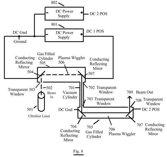
[025] Figure 8 is a general illustration showing an alternative of the third embodiment which provides an alternative method for cascading two plasma laser amplifiers by allowing separate power supplies for the two plasma laser amplifier sections to use a common ground.
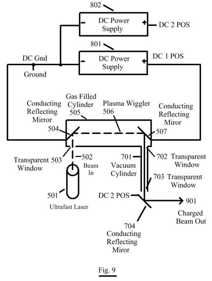
[026] Figure 9 is a general illustration showing the fourth embodiment which charges the output of the plasma laser amplifier to a potential that increases its effectiveness as a weapon.
[027] Figure 10 is a general illustration showing an alternative method of the fourth embodiment which charges the output of the plasma laser amplifier to a potential that increases its effectiveness as a weapon.
DETAILED DESCRIPTION
[028] In the following description, numerous specific details are set forth to provide a thorough understanding of the invention. However, it is understood that the invention may be practiced without these specific details. In other instances well-known circuits, structures, and techniques have not been shown in detail in order not to obscure the invention.
[029] Figure 1a shows the circular cross section (101) of a laser beam.
By using an ultrafast laser the pulse is very short so that the pulse is a very thin disk (101). This is shown in Figure 1b.
The natural tendency of the electrons being stripped from the gas atoms in the disk is to scatter randomly in all directions. This is shown in Figure 2a. Electron trajectories 201 and 202 are representative of the randomness that the electron trajectories would have if they could.
However, Coulomb repulsion causes the electrons to distribute themselves uniformly around the disk. This is shown in Figure 2b. Because the disk is so thin compared to its diameter most of the electron trajectories will be perpendicular to the disk and parallel to each other. Figure 2b shows the edge-on view. There will be many electron trajectories coming out of the disk shown in Figure 1b. The outside circumference of the disk will exhibit fringe effects analogous to the fringe effects of a long wire coil with an electric current running through it.
[030] Figure 3a is a general illustration showing the circular magnetic field produced by a single electron trajectory using the Right Hand Rule. Because we are looking at the motion of an electron the electron flow is into the paper.
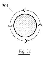
Figure 3b is a general illustration showing the circular magnetic fields produced by two electron trajectories.
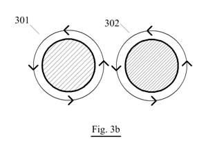
Figure 3c is a general illustration showing that the circular magnetic fields produced by two electron trajectories combine into a larger circular magnetic field.
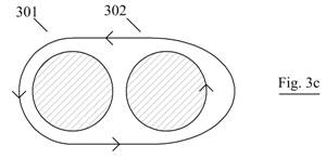
Figure 3d is a general illustration showing that the circular magnetic fields produced by a number of electron trajectories combine into a larger circular magnetic field.
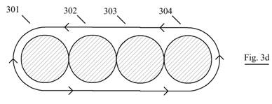
Figures 3a, 3b, 3c, and 3d are the same principles by which a coil of wire energized by an electric current produces the coil’s magnetic field, only the geometry is different.
[031] When all of the magnetic fields produced by the ultrafast laser pulse in the gas are combined the result is shown in Figure 4a. The leading edge of the pulse produces a strong magnetic field in one direction and the trailing edge of the pulse produces another strong magnetic field of the opposite direction.
As the pulse travels through the gas the leading edge will continue to produce its magnetic field and the trailing edge will continue to produce its magnetic field resulting in a series of alternating magnetic fields shown in Figure 4b. This provide a simple wiggler where the distance between the alternating magnetic poles is extremely short. This allows the coherent radiation produced by this wiggler to have a very short wavelength. The ionized beam produced by the laser conducts electricity so the driving energy is just a DC power supply.
[032] Figure 5a shows the first embodiment of the plasma laser amplifier. The output of Ultrafast Laser 501 produces Beam In 502 which enters Gas Filled Cylinder 505 through Transparent Window 503. Beam In 502 reflects off of Conducting Reflecting Mirror 504 sending Beam In 502 longitudinally through Gas Filled Cylinder 505 which is filled with a gas capable of being ionized. Thus reflected, Beam In 502 creates Plasma Wiggler 506 in Gas Filled Cylinder 505. Wiggler 506 is reflected off of Conducting Reflecting Mirror 507.
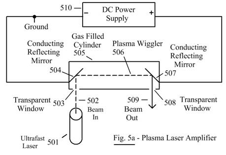
DC Power Supply 510 is connected between Conducting Reflecting Mirror 504 and Conducting Reflecting Mirror 507 and causes a current to flow through Plasma Wiggler 506 producing coherent radiation which is reflected off of Conducting Reflecting Mirror 507 and exits through Transparent Window 509. For the safety of the equipment and of the Operator best practice is to ground one side of DC Power Supply 510 although in cases where the voltage produced by DC Power Supply 510 is low enough DC Power Supply 510 may be left floating. In Figure 5a the negative terminal of DC Power Supply 510 is grounded.
In Figure 5b it is the positive terminal of DC Power Supply 510 that is grounded.
[033] Figure 6 shows the second embodiment of the plasma laser amplifier where two plasma laser amplifiers are cascaded. The output of Ultrafast Laser 501 produces Beam In 502 which enters Gas Filled Cylinder 505 through Transparent Window 503. Beam In 502 reflects off of Conducting Reflecting Mirror 504 sending Beam In 502 longitudinally through Gas Filled Cylinder 505 which is filled with a gas capable of being ionized. Thus reflected, Beam In 502 creates Plasma Wiggler 506 in Gas Filled Cylinder 505. Wiggler 506 is reflected off of Conducting Reflecting Mirror 507.
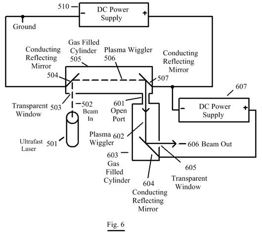
DC Power Supply 510 is connected between Conducting Reflecting Mirror 504 and Conducting Reflecting Mirror 507 and causes a current to flow through Plasma Wiggler 506 producing coherent radiation which is reflected off of Conducting Reflecting Mirror 507. This coherent radiation is also an ultrafast laser and provides the input to the second plasma laser amplifier through Open Port 601. Gas Filled Cylinder 602 is connected directly to Gas Filled Cylinder 506 through Open Port 601.
The output of the first plasma laser amplifier reflected by Conducting Reflecting Mirror 507 enters Gas Filled Cylinder 602 through Open Port 601 sends the beam longitudinally through Gas Filled Cylinder 602 which is filled with the same gas in common with the gas in Gas Filled Cylinder 505. The beam from the first plasma laser amplifier creates Plasma Wiggler 602 in Gas Filled Cylinder 603 which is reflected off of Conducting Reflecting Mirror 604.
A second DC Power Supply (DC Power Supply 607) is connected between Conducting Reflecting Mirror 507 and Conducting Reflecting Mirror 604 and causes a current to flow through Plasma Wiggler 602 producing coherent radiation which is reflected off of Conducting Reflecting Mirror 604 and exits through Transparent Window 605 as Beam Out 606.
Because DC Power Supply 510 and DC Power Supply 607 are connected in series DC Power Supply 607 must have the electrical insulation properties to withstand the combined voltages.
[034] Figure 7 shows the third embodiment of the plasma laser amplifier where two plasma laser amplifiers are cascaded but the two sections use a common power supply. The output of Ultrafast Laser 501 produces Beam In 502 which enters Gas Filled Cylinder 505 through Transparent Window 503. Beam In 502 reflects off of Conducting Reflecting Mirror 504 sending Beam In 502 longitudinally through Gas Filled Cylinder 505 which is filled with a gas capable of being ionized. Thus reflected, Beam In 502 creates Plasma Wiggler 506 in Gas Filled Cylinder 505. Wiggler 506 is reflected off of Conducting Reflecting Mirror 507.
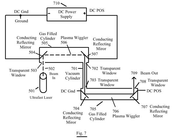
DC Power Supply 710 is connected between Conducting Reflecting Mirror 504 and Conducting Reflecting Mirror 507 and causes a current to flow through Plasma Wiggler 506 producing coherent radiation which is reflected off of Conducting Reflecting Mirror 507 and exits through Transparent Window 702. Transparent Window 702 is connected to Vacuum Cylinder 701 which ends in Transparent Window 703. This provides electrical isolation between the two plasma laser amplifiers which allows DC Power Supply 710 to power both plasma laser amplifiers.
The ultrafast laser output from Gas Filed Cylinder 505, having been electrically decoupled, comes into Gas Filled Cylinder 705 through Transparent Window 703 and reflects off of Conducting Reflecting Mirror 704 sending the beam longitudinally through Gas Filled Cylinder 705 which is filled with a gas capable of being ionized. Thus reflected, the beam produced in Gas Filled Cylinder 505 creates Plasma Wiggler 706 in Gas Filled Cylinder 705. DC Power Supply 710 is connected between Conducting Reflecting Mirror 704 and Conducting Reflecting Mirror 707 and causes a current to flow through Plasma Wiggler 706 producing coherent radiation which is reflected off of Conducting Reflecting Mirror 707 and exits through Transparent Window 708 as Beam Out 709.
If desired the gas in Gas Filled Cylinder 505 and Gas Filled Cylinder 705 may be different gasses. Additional sections may be cascaded all using the same DC Power Supply 710.
[035] In Figure 8 the two sections may be powered by two different power supplies, The first section (Gas Filled Cylinder 505) is powered by DC Power Supply 801 while the second section (Gas Filled Cylinder 705) is powered by DC Power Supply 802. This allows the two sections to be operated at different voltages. One reason for operating the sections at different voltages is to perform fine tuning such as for phase locking.
[036] Figure 9 shows the fourth embodiment that uses a single section plasma laser amplifier but where the output laser beam is electrically charged to provide increased lethality when it is used as a weapon. Vacuum Cylinder 701 and Transparent Window 703 provide the desired amount of electrical isolation. The output beam is reflected off of Conducting Reflecting Mirror 704 which is connected to DC Power Supply 802 in order to provide Charged Beam Out 901. The use of Vacuum Cylinder 701 and Transparent Window 703 allow Charge Beam Out 901 to operate at a very high voltage. The output beam from two or more cascaded plasma laser amplifiers may be charged using this same method.
[037] Figure 10 is also a single section plasma laser amplifier where the output laser beam is electrically charged to provide increased lethality when it is used as a weapon but the electrical isolation provided by Transparent Window 702 is sufficient and no further isolation is necessary.
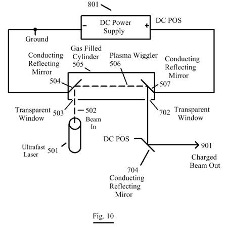
The output beam is reflected off of Conducting Reflecting Mirror 704 which is connected to DC Power Supply 801 in order to provide Charged Beam Out 901. This is the simplest method for charging the beam. However, if desired a second DC Power Supply can be used to charge Charged Beam Out 901 to a different voltage than the voltage used in the plasma laser amplifier.
[038] While preferred embodiments of the present invention have been shown, it is to be expressly understood that modifications and changes may be made thereto.
ABSTRACT OF THE DISCLOSURE
An ultrafast laser is used to produce a wiggler in a tube containing a suitable gas. The wiggler produced by the ultrafast laser is also electrically conductive. An electric current is introduced between the ends of the wiggler in the tube. The wiggler converts the electric current into coherent radiation.
References
Ref. 1: U.S. Patent No. 5,726,855 Apparatus and method for enabling the creation of multiple extended conduction paths in the atmosphere issued March 10, 1998 to Mourou, Braun, Diels, Bouvier, and Zhau.
Ref. 2: U.S. Patent 3,822,410 Stimulated emission of radiation in periodically deflected electron beam issued July 2, 1974 to Madey.
Ref. 3: U.S. Patent 4,283,687 Free electron laser with end tapered wiggler strength issued August 11, 1981 to Madey, Elias, and Smith.
Ref. 4: U.S. Patent 4,331,936 Free electron laser employing an expanded hollow intense electron beam and periodic radial magnetic field issued May 25, 1982 to Schlesinger, Marshall, McDermott, Granatstein, Parker, Sprangle, and Efthimion.
Ref. 5: U.S. Patent 6,377,436 Microwave transmission using a laser-generated plasma beam waveguide issued April 23, 2002 to Margolin.
Ref. 6: Plasma Wave Wigglers for Free Electron Lasers; Joshi, Dawson, Yan, and Chen, University of California, Los Angeles, CA; 1987; https://accelconf.web.cern.ch/accelconf/p87/PDF/PAC1987_0199.PDF
Ref. 7: X-ray Synchrotron Radiation in a Plasma Wiggler, Shuoqin Wang, Dissertation; University of California, Los Angeles; 2002;
www.seas.ucla.edu/plasma/files/Phd%20Thesis/2002_Wang_PhdThesis.pdf
Ref. 8: Beryllium Mirrors: Refinements Enable New Applications; Vladimir Vudler and Peter Richard; Hardric Laboratories, Inc. North Chelmsford, MA.
http://www.hardric.com/images/BeMirrors.pdf
.end