What I Have Learned About Propane Furnaces (The Hard Way)
or
The Mystery of the Flakey Furnace
Jed Margolin
This is about my experiences with a Ruud Model UGPH-07 EAUER gas furnace running on propane. It was manufactured in 1995.
Unless you have the knowledge and experience to safely work on this equipment (the voltage and the natural gas or propane) then you shouldn’t do it. You should have it done by a qualified professional. But even if you don’t do the work yourself the information may help you get your furnace fixed.
Index
B. I start to learn about gas furnaces.
C. The Ruud Control Board is replaced and the furnace works again. I examine the old board.
D. I make a schematic for the Ruud Control Board.
E. Now about the Control Board circuit, especially the Flame Sensor.
J. I invent a better flame sensing system
Details
A. My Ruud propane furnace stopped working. I didn’t want to learn all about gas furnaces, I just wanted to get it fixed by having someone else fix it. (It didn’t work out that way).
I live in the Virginia City Highlands, Nevada, which is in the mountains about 22 miles SE of Reno and five miles down the road from Virginia City. For pictures of my neighborhood click here.
It can get cold up here in Winter.
One morning in early December 2012 I woke up around 4 am to a cold house. Actually, it was just the upstairs that was cold. My house is two stories and I have two propane furnaces. One (100K BTUs) is in the garage for the first floor and the other (75K BTUs) is in the attic for the second floor.
Naturally, it was the furnace in the attic that wasn’t working. The blower was running but the air coming out of the vents was cold. The only way I could turn the blower off was to turn off the circuit breaker.
It was about 15 degrees Fahrenheit outside.
Although I am an engineer (electrical engineer) I didn’t want to try to fix the furnace myself. I just wanted to have an HVAC company come out and fix it and be done with it.
So, later in the morning I signed up for Angie’s List and called the HVAC company that was very highly rated. I will call them Company A.
Company A came out later in the day. Their Guy went into the attic, pulled the furnace panels and announced that the problem was that the limit switch had tripped. The limit switch is in the combustion compartment and opens if the temperature is too high.
I asked him what would cause the limit switch to trip. He said there were two main causes:
1. Dirty filters (Dirty filters reduce the airflow so the heat produced by the furnace isn’t being moved out fast enough);
2. A high wind had come through the attic (?). Presumably that would cause more propane to burn.
Neither explanation sounded right. My filters weren’t all that dirty and although there are times that we have 100 mph winds up here, that night wasn’t one of them.
The Guy reset the limit switch and cleaned the furnace, and the furnace worked again.
Note that when the limit switch opens, the control board shuts everything down except for the blower which it runs continuously.
B. I start to learn about gas furnaces.
1. Two days later, I again woke up in the early morning to a cold house. This time the symptoms were different. The furnace would come on and then immediately shut down.
Later in the morning I again called the Guy from Company A.
He wouldn’t come out. He said I should check the pressure switch. I don’t know why he wouldn’t come out again. I had paid him for the first service call and we didn’t have any snow on the roads (yet). Maybe he had a thing about attics.
That meant I had to do exactly what I didn’t want to do: get involved in fixing it myself.
I went into the attic, opened the furnace panels, and found the pressure switch. I disconnected the wires to the switch and connected an Ohmmeter to the contacts. When I sucked on the tube the contacts closed but there was a burbling sound. This was my first experience with a furnace pressure switch but I was pretty sure that it wasn’t supposed to burble.
By then I had discovered that the major distributor of HVAC and plumbing parts in Northern Nevada is Western Nevada Supply (http://www.goblueteam.com/). That’s where the HVAC service companies get their parts. Western Nevada Supply stocks just about everything you would need to install and fix HVAC systems. You can usually get equipment and parts cheaper online but then you have to wait for it to be delivered and people usually want their HVAC system fixed now.
I got a pressure switch for my furnace and, just for grins, a new flame rod and installed them. (I had already started learning about gas furnaces.)
2. A few days later, I again woke up in the early morning to a cold house. Same symptoms as the last time. The furnace would come on and then shut down.
This time I went to the Yellow Pages and picked out a company with a good ad, Cavallero Heating and Air Conditioning in Carson City (http://cavalleroheatingandair.com/) My mountain community is about as close to Carson City as it is to Reno.
Mike from Cavallero came out that day.
He verified that the new Pressure Switch and Flame Rod were good.
He noted that the Flame Good LED took an unusually long time to come on.
He separated the wire to the Flame Sensor from the bundle of wires it was in but it did not help. (Sometimes it does.)
He replaced the Igniter.
We decided that the only thing left was the Control Board.
He said I could probably buy one cheaper than he would have to charge me if he bought it. (He probably would have bought it from Western Nevada Supply, too.)
As he was getting ready to leave, it started to snow.
3. The next day I bought a new (and genuine Ruud) Control Board from Western Nevada Supply Company. By then it was snowing even in Reno. (My house is at an altitude of about 6,000 feet. It snows here first, and sometimes it snows here but not in Reno.)
Due to the snow, the roads in the Highlands became icy and weren’t safe without a vehicle that could handle an icy hill. I didn’t want Cavallero to risk the roads. And I didn’t want to replace the Control Board myself. (Ok, I was spooked by my furnace.)
Besides, by then I had discovered that the furnace would work ok until the outside temperature dropped below 20 degrees. At that point the attic temperature would be in the high 30s.
I wondered if the Control Board was too cold so I tried running the blower to warm the Control Board with air from the house. No joy. As it turned out, if I had run the blower longer it might have worked.
While I was waiting for the roads to clear I called my propane company (Bi-State) and they came out and checked the propane pressure at the furnace with both furnaces running. Bi-State can get through no matter how bad the roads are.
The propane pressure was good.
And I did something else.
The Control Board has three LEDs on it.
1. Power: We have Power.
2. Flame Good: The Flame Sensor says we have a good flame.
3. Diagnostic Code: If there is a problem it flashes a code. The number of flashes indicates the problem.
Newer furnaces have a window in the cabinet panel so you can see the LEDs without taking the panel off.
Mine didn’t have one so I cut a hole in the panel and put a square of clear acrylic sheet over it. The control board is in a plastic box with a metal cover so I also cut a hole in the metal cover and covered it with acrylic.
That way I could see the LEDs without removing the panel. And since the furnace is in the attic I pointed a wireless surveillance camera at the LEDs so I could see them without going into the attic.
C. The Ruud Control Board is replaced and the furnace works again. I examine the old board.
1 After ten days of moderate winter temperatures (for the Highlands) the forecast called for nighttime temps in the teens.
I called Cavallero and they agreed to come out even though the roads were still icy.
Chris came out and installed the new board. When he fired up the furnace the Flame Good LED came on immediately with the flame with no delay.
This turned out to be an important clue because, with the old control board, the Flame Good LED took an unusually long time to come on. It could take as long as 20 seconds.
2. Since I was already involved and had spent a fair amount of money on it I wanted to understand the problem in case it happened again. I started with a physical examination of the control board.
a. The old control board (62-24084-01) has been superseded by a new board (62-24084-82). However, they are both made the same way. I suspect that the difference is a software update in the microcontroller, a PIC16C57 by Microchip (http://www.microchip.com/wwwproducts/Devices.aspx?product=PIC16C57). For the datasheet click here.
b. The control board is a single-sided Printed Circuit Board (PCB).
The following pictures are from:
This is what a single-sided PCB looks like.
The copper (and therefore the traces) are on only one side of the board.
Figure 1
![[​IMG]](index_files/image001.jpg)
Here is a double-sided (double Layer) PCB. The traces are on both sides of the board.
Figure 2
![[​IMG]](index_files/image002.jpg)
The advantages of the double-sided PCB include:
a. You have more room and flexibility to run traces. In a single-sided PCB you are much more likely to have to use wire jumpers on top of the board in order to complete some of the circuits.
Since you have more room you have a better chance of being able to have good Grounds. When Grounds use thin traces you have more electrical noise. Wide traces (and large copper areas) make for less noise in the Grounds.
b. All of the holes are plated through, even the ones that do not have traces on both sides of the board.
When you solder a wire in a plated through hole the solder wicks into it, filling the hole as shown above.
This provides a stronger mechanical connection for the part. Here is why you want a strong mechanical connection for the parts.
a. If the board is subject to mechanical vibration the parts will vibrate and put mechanical stress on the soldered joints. It might break soldered joints. Note that the control board is mounted in the blower compartment where it is subject to vibration whenever the blower is on.
b. If the board has a connector and you unplug the connector you may be putting a large amount of force on the soldered joints. For this reason, when you are unplugging a connector you should try to hold on to the connector body on the board to reduce the force on the soldered joints.
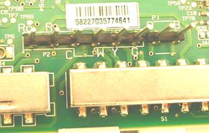
The Ruud control board has two connectors, the larger one having nine pins. (You can also see several wire jumpers on top of the board.)
Figure 3
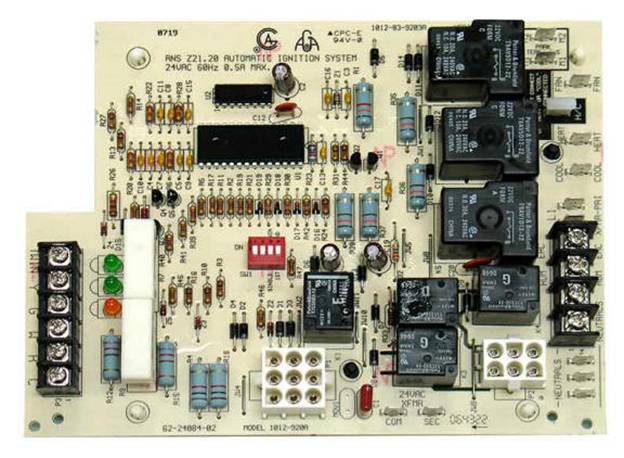
Ruud’s use of a single-sided PCB explains why the connectors have a reputation for damaging the PCB joints when you unplug the connector.
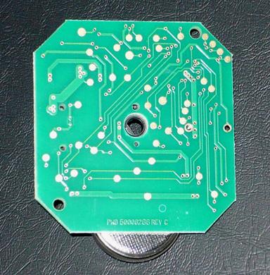
This is the bottom of the board.
Figure 4
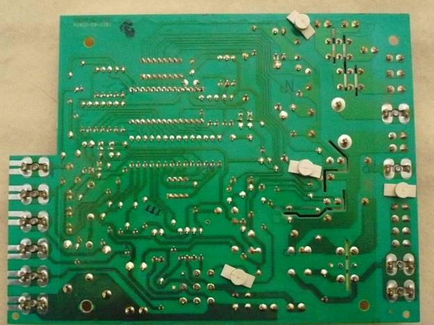
There are some generous ground areas but they are only for high-current mains traces. The grounds for the PIC16C57 microcontroller and associated circuitry are wimpy.
Note that there are a few slots in the board. They are there to provide positive isolation between mains power and the lower voltage circuits.
Since I have another Ruud furnace downstairs that was also made in 1995 I decided to be proactive and get another control board for it. I found one online really cheap and bought it. I thought I was buying another Ruud board but it turned out to be a replacement board (ICM288) made by someone else. It was made by ICM Controls (http://www.icmcontrols.com/) It turned out to be a lucky mistake.
The ICM288 is pretty much fit and function compatible with the Ruud 62-24084-82. (The diagnostic LEDs are not exactly in the same place so they might not be visible through a window.)
The ICM288 is a really nice board.
a. It is a two-layer board with good ground coverage.
b. It uses many surface mount devices (SMDs) so most of it can be stuffed and soldered by machine. This method of manufacturing helps keep the cost down. The large parts would still have to be stuffed by hand. They would probably be stuffed and soldered separately after the SMDs were soldered. Notice that in the lower left there are some resistors mounted in cutouts in the board. This provides better airflow to cool the resistors.
Figure 5
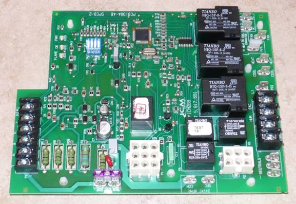
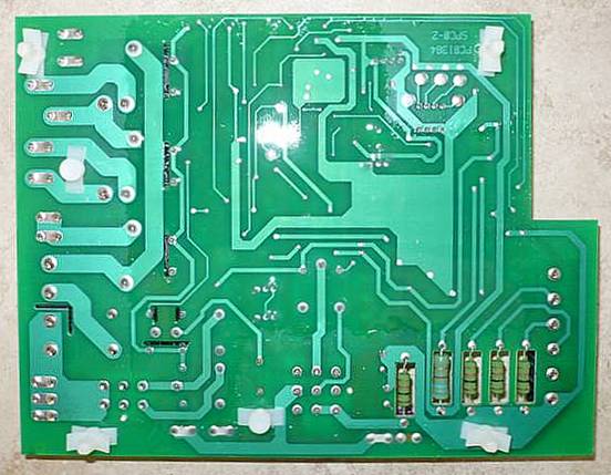
Figure 6
For the documentation on the ICM288 board click here.
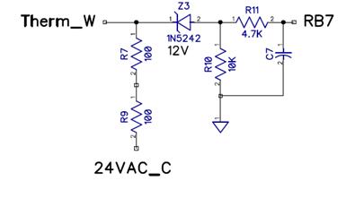
D. I make a schematic for the Ruud Control Board
I wanted to know how the control board is supposed to work so I followed every trace to every pin on the old Ruud board and made my own schematic.
For my schematic click here. (The wiring diagram for the furnace is from the Ruud manual.)
Before I discuss the circuit design, for the Ruud GHP Series Installation manual click here.
It contains useful information about how the furnace is supposed to work.
From PDF pages 24-25:
This is for the unit with the Hot Surface Ignition as opposed to the Spark Ignition.
1. Each time the thermostat contacts close, the induced draft blower (inducer) begins a prepurge cycle.
2. The air proving negative pressure switch(es) closes.
3. Five seconds after the pressure switch(es) close, the hot surface igniter begins heating for 30 seconds to full temperature. The induced draft blower operates for the complete heating cycle.
4. After the 30-second igniter warm up, the gas valve opens for an eight second trial for ignition.
5. The igniter lights the gas burners and stays energized for the first eight seconds after the gas valve opens.
6. Seven seconds after the gas valve opens the remote flame sensor must prove flame ignition for one second using the process of flame rectification. If the burners don't light, the system goes through another ignition sequence. It does this up to four times.
7. The main blower starts 20 seconds after the burners ignite.
8. When the thermostat cycle ends, the gas valve closes, the burners go out, the induced draft blower runs for a five second post-purge, and the negative pressure switch(es) open.
9. The main blower continues until timed off by the setting on the integrated furnace control board.
10. [My comment: If, at any time after ignition the flame sensor indicates No Flame, the gas valve is turned off and the furnace shuts down after running the Blower for awhile.]
This is the sequence if the system doesn't light or doesn't sense flame:
1. On a call for heat, the control runs the inducer for 30 seconds to prepurge.
2. Five seconds into prepurge, the hot surface igniter begins heating for 30 seconds. The inducer continues to run.
3. After the 30-second igniter warm up, the gas valve opens for an eight second trial for ignition. The inducer continues and the igniter stays energized.
4. If flame is not sensed during the eighth second after the gas valve opens, the gas valve closes, and the igniter de-energizes.
5. After five seconds of inter-purge, the igniter heats for 30 seconds. After 30 seconds, the gas valve opens for nine seconds. If no flame is sensed, it closes the gas valve, the igniter de-energizes, Both the main blower and the inducer operate for 180 seconds before the next ignition trial.
6. It repeats this process up to four times. At the end of the last try, the inducer stops immediately. The system is in "soft" lock out for one hour.
7. The above sequence will repeat after a one hour delay. It will continue repeating until ignition is successful or the call for heat is terminated.
8. To reset the lock out, make and break power either at the thermostat or at the unit disconnect switch for 5 to 10 seconds. It then goes through another set of trials for ignition.
There is also the Limit Switch (PDF page 29):
SAFETY FEATURES
LIMIT CONTROL
The high limit cut-off temperature is set at the factory and cannot be adjusted. The temperature setting prevents the air temperature leaving the furnace from exceeding the maximum outlet air temperature, which, if exceeded, will shut the furnace down. Some reasons which could cause the outlet temperature to exceed the range include: failed indoor blower, dirty filters, etc.
OVER TEMPERATURE SAFETY SWITCHES
Furnaces are equipped with safety switches to protect against overtemperature conditions in the burner compartment, which, if tripped, will terminate the heating cycle. In the event of an overtemperature condition, the switch will shut the furnace down. The switch for the dedicated UPFLOW FURNACE and DOWNFLOW is located just above the burners on the blower divider panel. Switches for the UPFLOW/ HORIZONTAL FURNACES are located on either side of the burner brackets and just above the burners on the blower divider panel. If a switch is tripped, it must be manually reset. DO NOT jumper or reset this switch. If this switch should trip, a qualified installer, service agency or the gas supplier should be called to diagnose and/or correct the source of tripping. If this unit is mounted in a closet, the door must be closed when making this check.
It doesn’t mention that when the limit switch trips it runs the blower continuously until you do a power-reset of the furnace.
I mentioned that one of the LEDs on the Control Board is a Diagnostic LED. If there is a problem it is supposed to blink a code as follows (from PDF page 34):
|
One Blink followed by a 2 second pause |
One Hour Lockout |
|
|
|
|
Two Blinks followed by a 2 second pause |
Pressure Switch is open |
|
|
|
|
Three Blinks followed by a 2 second pause |
Limit Switch is open |
|
|
|
|
Four Blinks followed by a 2 second pause |
Pressure Switch is closed |
The ICM Control Board has additional fault codes. And, as it turned out, the Diagnostic LED on my old Ruud Control Board never blinks a code no matter what the fault is except for a Twinning error. Then it flashes continuously.
E. Now about the Control Board circuit, especially, the Flame Sensor.
It is very important to be able to detect that a flame is actually being produced when the gas valve is on. Otherwise the unburned fuel will continue to flow and build up. It may cause asphyxiation, and if it finds an ignition source it may explode. Boom! There goes your house. And maybe you, too.
1. There are two main methods used to detect flames.
a. One method uses an optical detector to look at the ultraviolet light produced by the flame. Flames produce a broad spectrum of energy from infrared to ultraviolet. Although sensors for infrared or visible light are much cheaper than ultraviolet sensors, an infrared or visible light sensor could be fooled because the walls of combustion chambers tend to radiate visible and infrared energy for a period of time after the flame is lost. On the downside, Ultraviolet Flame Detectors are very expensive.
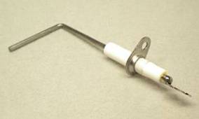
b. The other method uses the electrical properties of a flame by placing a metal rod in the flame (or where the flame is supposed to be). The flame rod is just a metal rod in a ceramic insulator that allows it to be mounted to the cabinet without shorting out the rod. Flame Rods are cheap. (Guess which one is in your home furnace.)
Figure 7
If you have never seen a combustion burner this is what one looks like.
Figure 8
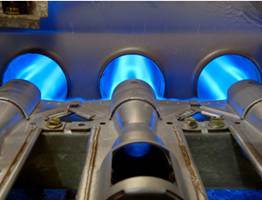
A combustion burner is a tube with a hole that allows the air to mix with the gas before it is burned. For that reason it is called a premixed flame. (The flow of the gas sucks in the air. If the tube is vertical then the heat differential can also help suck in the air.) There are flames that are not premixed, they are called diffused flames. A candle has a diffused flame because the air diffuses into the gas (the wax vapor/gas) at the flame. A diffused flame is less efficient than a premixed flame.
Note that in the above picture the ends of the gas tubes are shaped somewhat like a rocket engine. The ones in my furnace are straight.
Also note that there are three flame tubes. The flames are aimed at a heat exchanger to heat the air circulating through your house. (You don’t want to have the products of combustion in your house.) A single large flame would create a single large hot spot. Using multiple flame tubes distributes the heat more evenly along the heat exchanger. It also allows the furnace manufacturer to make several models of a furnace that differ only by the number of flame tubes and therefore its BTU heating rating. The furnace in my attic is 75K BTUs and has three combustion tubes. The furnace in my garage is 100K BTUs and has four combustion tubes.
Now we have a flame rod and a combustion burner. The return current path for the flame is through the combustion burner which is attached to the cabinet, which by definition is ground. For safety, all exposed metal parts of an appliance must be grounded. Also for safety, the gas line connected to the combustion burner must be grounded.
Now here’s the thing.
The electrical characteristics of a flame cause current to be conducted preferentially in one direction over the other. This is commonly called “flame rectification” and the flame is called a “flame rectifier” or “flame diode”. That gives the flame too much credit. It is not a very good diode. Here is an equivalent electrical circuit with representative values.
Figure 9
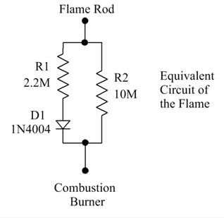
Because the flame is not a very good diode, the way it is used requires a substantial voltage to produce a usable effect. In my furnace Ruud uses the raw 120VAC Mains. (That seems to be standard in most consumer furnaces because it is the cheapest way to do it.)
Figure 10

I have a problem with this.
Because the combustion burner is Ground, it means that the Mains Neutral must also be connected to Ground.
According to the National Electrical Code this may only be done (and is required to be done) at the service entrance to the building and no place else. As a result, an electrical connection problem outside the furnace at the service entrance may cause a flame sensing circuit to malfunction even though there is no problem in the furnace itself.
How could this happen?
Maybe you have an old house and the Mains Neutral was never connected to Ground.
How could your furnace ever work like this?
The current through the flame circuit is on the order of several tens of microamps. The National Electrical Code allows a leakage current between Ground and Neutral of 4 milliamps to 6 milliamps. Above that, a Ground Fault Interrupter is required to trip. That is so you won’t get electrocuted in your bathroom by a faulty blow dryer.
Four milliamps is 100 times greater than, for example, 40 microamps.
You could have an appliance such as a washing machine that has a ground leakage current of 4 milliamps. Your flame sensor circuit will work. Then you get a new washing machine with no detectable leakage and your furnace will stop working.
If you replace the washing machine at the beginning of the Summer and don’t use your furnace until several months later you might miss the amazing coincidence.
Here is another thing that could happen.
Suppose the Mains Neutral and Ground wires at your service entrance (outside the house) are of a mixed type. One is Copper and the other is Aluminum and the terminal block where they are connected is not rated to handle the mix of Aluminum and Copper.
Now you have a really cold night and the terminal block connector cannot handle the different thermal expansion rates of Aluminum and Copper. One expands too much (or too little) and is no longer connected. Your flame sensor (and furnace) will fail to work just when you need it the most.
And later that day when you have Furnace Repair Guy come over the temperature has come up (it’s daytime) and now the furnace works. Bummer.
My other objection to having the furnace send the flame current through the Ground wire is that it is sending a signal through the Ground Wire. I think Ground should be used only for Ground.
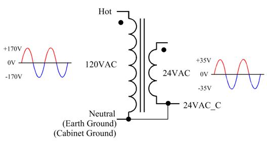
2. Since we will be testing the flame sensor there is an important matter to consider.
The circuit ground in the circuit that measures the voltage produced by the flame sensor is not the same as the 24VAC Common/Cabinet/Combustion Burner/Mains Ground/Neutral.
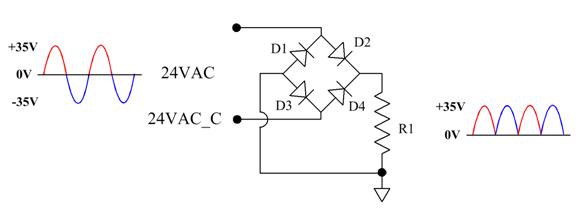
From the Schematic Page 3 note that the 24VAC goes to a bridge rectifier but the output is not filtered, so all the relays operate on pulsating DC. When you rectify 24VAC you get a pulsating +35V.
Figure 11
That’s not the problem. It’s just strange.
The +35PV gets zenered down and filtered for the +5V (VDD) for the microcontroller. Notice that D5 is needed because the +35PV is not filtered.
Figure 12
That’s not the problem either.
The problem is that the 24VAC Common/Cabinet Ground/Mains Neutral/Mains Ground is not the same as the Circuit Ground used by the microcontroller.
Figure 13 (From Figure 11)
Note that the symbol for Circuit Ground is:
![]()
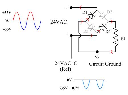
This is what happens.
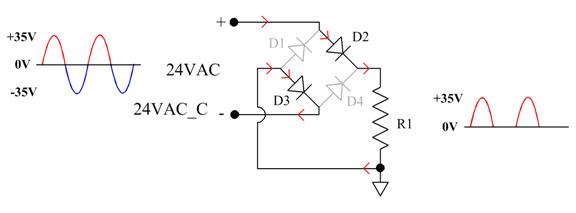
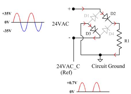
During the positive half-cycle of the 24VAC the current goes through Diode D2, Load R1, and Diode D3. (The waveform is across Load R1.)
Figure 14
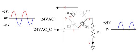
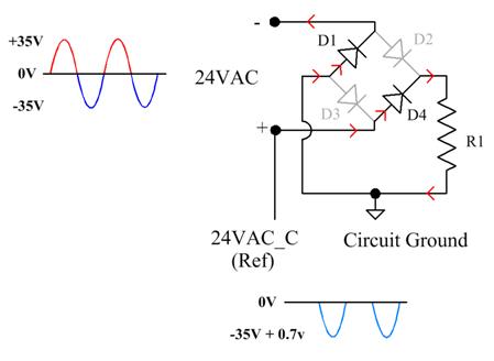
During the negative half-cycle of the 24VAC the current goes through Diode D4, Load R1, and Diode D1.
Figure 15
The result is full-wave rectification of the 24VAC. That is how a bridge rectifier works.
Figure 16
The problem is that there is a diode between Circuit Ground and 24VAC_Common (Cabinet Ground/Mains Neutral/Mains Ground).
On the positive half-cycle Diode D3 is on so there is only a diode drop (about 0.7V) between 24VAC_Common (etc.) and Circuit Ground.
Figure 17
However, on the negative half-cycle Diode D3 is off and there is almost -35PV between 24VAC_Common (etc.) and Circuit Ground.
Because of this whenever the microcontroller (referenced to Circuit Ground) must read a signal referenced to 24VAC_Common the signal must be shifted and limited. (All of the signals from the thermostat are referenced to 24VAC_Common.) This is how it is done:
Figure 19
The relays are run from the +35PV whose return is Circuit Ground so no level
shifting is necessary. Integrated Circuit U2 contains transistors with
uncommitted open collectors and a common emitter connection which is grounded
to Circuit Ground.
Figure 20
The relay circuit for the Gas Valve has something extra.
Figure 21
The control must be continuously toggled in order to keep the relay energized. If it sticks either high or low the relay will open. You really don’t want the Gas Valve open unless you really want the Gas Valve open. The Inducer Blower relay has the same circuit. (If the Inducer Blower turns off, the Pressure Switch will open and the furnace will shut down.)
F. I make a Test Fixture
Important Note:
Because Circuit Ground and 24VAC_Common have a substantial voltage between them you have to careful when you measure voltages and waveforms on the board.
1. 24VAC_Common is connected to 120VAC Mains Neutral.
2. If you use an oscilloscope, the oscilloscope ground will already be connected to Mains Ground through the three-prong power cord. If you connect a probe ground to Circuit Ground you will send current through the probe ground and probably burn it out. Or burn something else out. (Do Not float the oscilloscope.)
3. If you use a two-channel oscilloscope and connect one of the probe grounds to Circuit Ground and the other probe ground to 24VAC_Common you will obviously have the same problem. You will still have the problem if you float the oscilloscope (Do Not float the oscilloscope) or put the oscilloscope on an isolation transformer.
To avoid this I made a Test Fixture with switches to simulate the various furnace systems and LEDs to show the actions performed by the Control Board. Since the 120VAC Mains just goes through relay contacts to provide power to the Inducer Blower, Igniter, and Main Blower (and those are represented by LEDs) I used a safe 12VDC instead.
For the schematic of this Test Fixture click here.
1. Note that the 24VAC transformer has to be connected to the 120VAC Mains with its own plug since the Neutral and Hot blades on the Control Board will have 12VDC on them.
2. Also note that since I do not have 120VAC on the Control Board I spoof the Flame Circuit with a 9V battery. The circuit has to be connected to the proper places on the Board. I made the voltage adjustable in order to investigate the operation of the Flame Circuit.
Figure 22
The voltage produced by the Flame Sensor circuit is either 0 Volts (no flame) or negative (a flame). Q1 is an N Channel JFET (Junction Field Effect Transistor). At zero gate voltage JFET Q1 is On and RC6 is Low. A sufficiently negative gate voltage turns Q1 off which makes RC6 High. The negative voltage produced by the Flame Sensor is used to charge capacitor C17.
Q2 is a P Channel JFET. A P Channel JFET is the Bizarro World version of the N Channel JFET. Everything is opposite. Instead of controlling a positive voltage between the Drain and the Source, a negative voltage is controlled. Instead of a negative gate voltage turning it off, a positive gate voltage turns it off. This allows a positive voltage produced by the microcontroller (RC7) to turn Q2 on, which discharges Capacitor C17.
The microcontroller does not have enough I/Os for everything so they are cleverly multi-purposed. When RC7 is Low, Q2 is On which discharges Capacitor C17. When RC7 is Low it also grounds one side of DIP Switches 1-4. This allows DIP1 to be read by RC5, DIP2 to be read by RC4, DIP3 to be read by RC3, and DIP4 to be read by RC2.
When RC7 is High, Q2 is Off which allows Capacitor C17 to be charged by the Flame Voltage. It also stops grounding the DIP Switches which allows RC5, RC4, RC3, and RC2 to do other things. RC5 becomes an output to control the Flame Good LED, RC4 becomes an output to control the Diagnostic LED, RC3 becomes an output to control Twinning, and RC2 remains an input but monitors the Limit Switch.
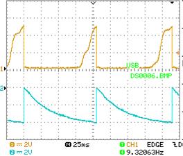
The Flame Sensing Circuit in Action
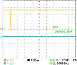
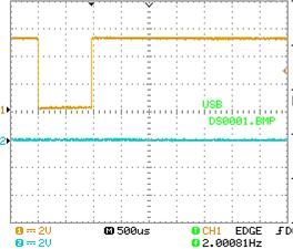
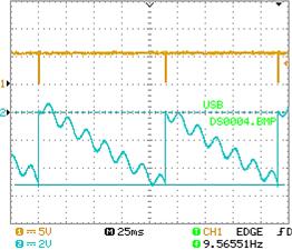
In the following figures the top trace is RC7 and the bottom trace is the Flame Voltage at C17. RC7 is normally high so Q2 is off. When there is no flame the voltage at C17 is 0V. Q1 is On and RC6 is Low.
However, RC7 pulses Low every 500 ms (1/2 second) to check the DIP Switches. It also discharges C17 in case it is holding a small charge.
Figure 23
The pulse width is 1,000 us (1 ms):
Figure 24
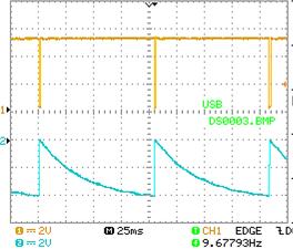
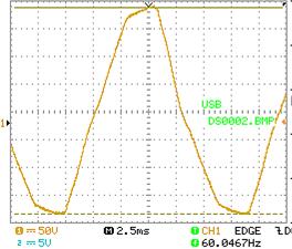
When the Flame Voltage is negative enough to turn Q1 off, RC6 goes high and the RC7 pulse happens more frequently. The rate of the RC7 pulse depends on how long it takes the Flame Voltage to reach about -4V. When it is about -4V the time is about 105 ms.
Figure 25
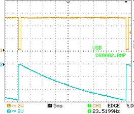
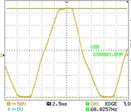
When the Flame Voltage is more negative, then the RC7 pulse ends sooner. Here it is at about -6V. The time is about 43 ms.
Figure 26
In the following figures the top trace is RC6 and the bottom trace is the Flame Voltage at C17.
With a healthy Flame Voltage of -6V the RC6 pulse width is about 19 ms.
Figure 27
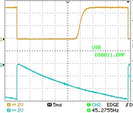
But with a Flame Voltage of only -4V the RC7 pulse is right at the edge of usability.
Figure 28
The voltage at which an N Channel JFET begins to turn off is called the Threshold Voltage (or the Gate-Source Cutoff Voltage). The Threshold Voltage is different for different type numbers of JFETs.
The number on Q1 is “N512” but I haven’t found a datasheet for it. A representative N Channel JFET is the Fairchild J111. According to the datasheet (click here) the Threshold Voltage for the J111 is about -3V. (PDF Page 2) For other members of the series it is -1V (J112) and -0.5V (J113).
The Threshold Voltage of a JFET changes with temperature in a complicated manner. I used Freeze Spray on Q1 but it did not change the RC7 period by much. Importantly, the Flame Detect did not stop working. Since Freeze Spray says it cools components down to -65 degrees Celsius (-85 degrees Fahrenheit) it is clear that my cold attic did not affect the Q1 threshold voltage.
I thought I was on to something when I measured R32, which is supposed to be 22M. It measured 36M. I didn’t have any 22M resistors so I put together a replacement with two 10M resistors and a 1M resistor. (One of the 10M resistors was high.) Separately they measured within tolerance but together they measured 32M. What?
I was using an old Wavetek DM27XT and measuring above 20M meant switching to a higher scale. I changed to a very old Micronta (Radio Shack) DVM and the 22M measured 26M. The combo of 10Ms and 1M measured properly as 21.6M. I confirmed it with a Greenlee DM-300. I thought that my Wavetek DM27XT was an accurate meter but I guess it isn’t, at least for high resistances.
The difference in R32 between 22M and 26M would not explain the failure of the Ruud board to recognize the flame in a timely manner in my cold attic.
I used the Freeze Spray on the original R32. It went from 26.66M to 30.51M for an increase of 14%. When I used the Freeze Spray on one of the 10M resistors it went from 10.80M to 11.02M for an increase of 2%. Since both are carbon film resistors something is not right with the 22M resistor. Still, it also doesn’t explain the failure of the Ruud board to recognize the flame in a timely manner in my cold attic.
The microcontroller (PIC 16C57) clock uses a resistor (R23) and capacitor (C13) to set the frequency. It’s a really cheap way of doing a clock. It drifts with temperature as the resistor and capacitor drift with temperature. (The ICM288 uses either a crystal or a resonator.) I measured the clock output at pin 26 (which is 1/4 the internal clock) at 503 KHz. Using Freeze Spray on R23 and C13 changed it to about 480 KHz, a decrease of almost 5%. That wouldn’t explain the problem either, especially considering how cold the Freeze Spray is.
Before we leave the Flame Sensing circuit I will note that the Flame Sensing Circuit works all the time regardless of the state of the furnace.
The microcontroller is smart enough to know that if the Flame Sensing Circuit says there is a flame when there shouldn’t be one (like if the Gas Valve is closed) it goes into Safe Mode and will turn on the Inducer Blower and the Main Blower. It also flashes the Flame Good LED rapidly and continuously.
The Flame Sensor Circuit could indicate a flame if the furnace has been on but, when it was instructed to turn off, the Gas Valve has stuck open. In that case the best thing to do is to assume there really is a flame.
Of course, if there really is a flame and it cannot be turned off, your house is going to get very warm.
Even worse is if the Gas Valve gets stuck open without a flame. This could happen if the Igniter is broken, the furnace tries to start, doesn’t get a flame, and then the Gas Valve sticks open.
If this happens, hopefully you will smell the gas in time to get out. (Get Out, don’t investigate, don’t turn on any lights, just Get Out.)
I suspect that gas furnace explosions do not happen very often.
Most of the discussions on the Cortex about gas appliances exploding are about water heaters. In particular, if there is a flood the springs in the Gas Valve can become corroded.
However, since many gas furnaces are located next to gas hot water heaters, if there is a flood it could affect the gas valves in both units. (If you have a flood that bad you will have more problems than just your furnace.)
H. I investigate the possibility that the phase of the 24VAC transformer makes a difference in how well the Flame Circuit works.
Transformers have a phase. They can either maintain the phase between the primary and and secondary windings or they can invert it. Frequently transformers are marked with a dot to indicate phase.
This one is in phase.
Figure 29
This one is out of phase.
Figure 30
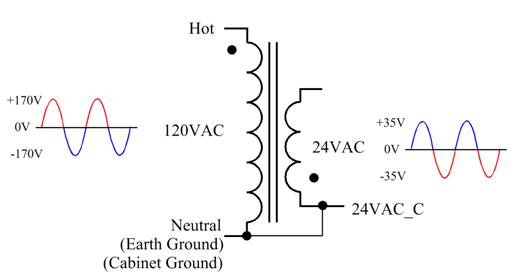
The primary is connected to the 120VAC Mains which is used by the Flame Sensor.
The secondary gets rectified but the 24VAC_Common is not the same as the Circuit Ground which provides the reference for reading the Flame Voltage.
During half of the wave it can be different by as much as 35V. This is a reproduction of Figure 18.
Figure 31
In order to investigate I needed to operate the Control Board at 120VAC, so I reworked my test fixture. Click here.
Note that for safety I ran it from an isolation transformer. Also note that:
a. A Variac is not an isolation transformer.
b. You can make a simple isolation transformer from two transformers connected back-to-back. I used two 24VAC 3A transformers. Click here. This method loses efficiency so the voltage you get out will be a few volts lower than what you put in. It is for the test fixture only. It won’t power a furnace.
c. If you want a real isolation transformer the Triad N-68X looks good. They say that “the primary and secondary windings are precision wound on separate arbors, then assembled on a laminate core side by side separated by insulation.” If the primary and secondary windings are wound concentrically you could have a short between them. Concentric windings also have capacitive coupling between them. As of this writing Allied Electronics is selling the N-68X for $13.13 . http://www.alliedelec.com/triad-magnetics-n-68x/70218526/?mkwid=sabYU23qn&pcrid=30980760979&gclid=CPP8soaFhskCFYZlfgodM4UFAw#tab=specs
I also made a Flame Spoofer to simulate the electrical characteristics of the flame. I put it on a switch for reasons that will become apparent soon.
Here is the theory.
The voltage that is used for the Flame Sensor comes from the 120VAC Mains whose ground reference is 120VAC Neutral (24VAC_Common) but the reference used to measure the Flame Voltage comes from Circuit Ground which is different from 120VAC Neutral. (See Figure 17 and Figure 18 for why this happens.)
In one half-wave the voltage between 24VAC_Common and Circuit Ground will be almost 0V and in the other half-wave it will be almost 35V.
In the following figures remember that the flame conducts current preferentially in one direction, the positive direction. This property is used to shunt the positive voltage to ground (somewhat) but not the negative voltage. This gives a net result of a negative voltage to be detected. (The Red Circuit Ground is the Circuit Ground during the positive half-cycle, the Blue Circuit Ground is the Circuit Ground during the negative half-cycle.)
When the 24VAC transformer is phased one way it will be:
Figure 32
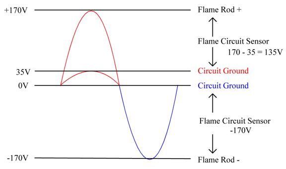
This reduces the positive voltage but not the effective negative voltage. That should be considered good.
When the 24VAC transformer is phased the other way it will be:
Figure 33
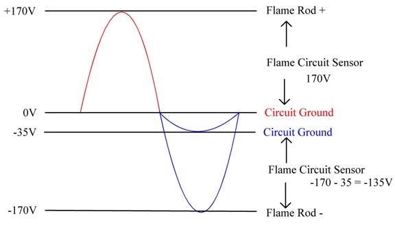
This reduces the effective negative voltage but not the effective positive voltage. Not good.
How does this work in real life?
1. Referring to Figure 22, C20 provides AC coupling to the half-wave waveform in Figure 18.
The average voltage of a half-wave rectified waveform is Vpeak/pi.
Figure 34 (from Figure 18)
After C20:
Figure 35
As a result of the filtering done by C17 and the various resistances in the circuit we get an asymmetrical sine-like wave. (See Figure 45 later on.)
I have done a bunch of tests on my board to show the effect of having the Flame Sensor referenced to 120VAC Mains/24VAC_Common while the circuit used to measure the flame voltage uses the Circuit Ground as a reference. Then I reversed the phase of the 24VAC transformer to see what effect it has.
120VAC and 24VAC - In Phase
Figure 36
This is before C20: Max = +170V, Min = -128V
Figure 37
This is after C20: Max = +152V, Min = -134V
Figure 38
120VAC and 24VAC - Out of Phase
Figure 39
This is before C20 (I moved the 0V point so it would fit on the screen without reducing the scale):
Max = +208V, Min = -164V, Sum = 44V
Figure 40
This is after C210: Max = +188V, Min = -168V
Figure 41
Summary
|
120VAC in phase |
Max (V) |
Min (V) |
Sum (V) |
|
Before C20 |
+170 |
-128 |
+42 |
|
After C20 |
+152 |
-134 |
+18 |
|
120VAC out of phase |
Max (V) |
Min (V) |
Sum (V) |
|
Before C20 |
+208 |
-164 |
+44 |
|
After C20 |
+188 |
-168 |
+20 |
Therefore:
1. When the 24VAC transformer is in phase with the 120VAC, the voltage after C20 (which feeds the flame rod) has a sum of 18V. This means that when C17 sums the voltage from the flame sensor, having Flame Ground and Circuit Ground at different voltages creates an offset of +18V. Although the full 120VAC goes to the flame rod, the circuit used to measure the flame voltage has its reference at 18V. This effectively subtracts from the 120VAC Mains so the voltage that goes to the flame rod is effectively reduced to 120 - 18 = 102V.
2. When the 24VAC transformer is out of phase with the 120VAC, the voltage after C20 (which feeds the flame rod) has a sum of 20V. This means that when C17 sums the voltage from the flame sensor, having Flame Ground and Circuit Ground at different voltages creates an offset of 20V. Although the full 120VAC goes to the flame rod, the circuit used to measure the flame voltage has its reference at 20V. This effectively subtracts from the 120VAC Mains so the voltage that goes to the flame rod is effectively reduced to 120 - 20 = 100V. That is not much of a difference.
The next step is to look at the circuit in action.
Although the input impedance of my ‘scope probes is very high (10M) the impedance of the flame circuit is even higher (22M).
To properly measure the circuit I made a very high impedance buffer using a TL062 and powered it from a 12V Gel Cell that I have. For the circuit Click here.
Does the phase of the 24VAC transformer make a difference?
The short answer is No.
For these tests:
1. The voltage is referenced to Circuit Ground.
2. The top trace is RC7 and the bottom trace is the Flame Voltage at C17.
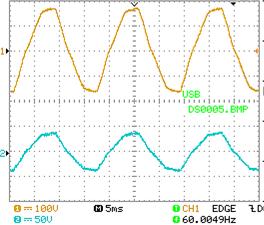
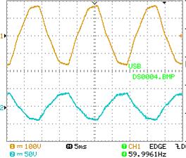
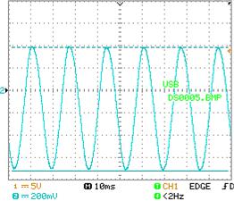
In the following figure the Flame Spoofer is turned on.
The waves in the bottom trace (the Flame Voltage) are caused by the differences in references discussed above. I will call it the Nurble. The pulsating DC (Figure 35) is being smoothed by C17 and the various resistances in the circuit.
The Flame Voltage ramp goes from 0V to -4.88V.
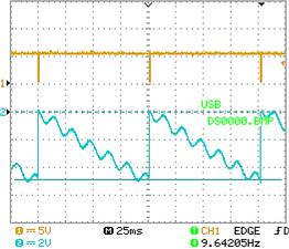
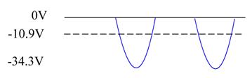
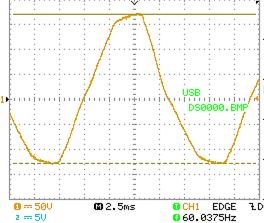
In this test the Flame Spoofer is turned off so we can get a better look at the Nurble.
The Nurble goes from +0.408V to -0.488V.
Figure 43
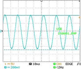
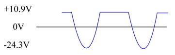
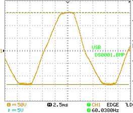
I repeated the test after reversing the phase of the 24VAC transformer.
The Flame Voltage ramp goes from 0V to -4.88V (the same as the first test).
What is different is the Nurble. It goes from +0.384V to -0.720V.
Figure 45
If the Nurbles are different, why is the overall Flame Voltage ramp the same?
What is not shown is that the Flame Voltage ramp jitters. The reason for the jitter is because the Nurbles are not synchronized to the Flame Voltage ramp. In Figure 44 you can see that the first Flame Voltage Ramp starts with a positive half-cycle of the Nurble while the second Flame Voltage ramp starts with a negative half-cycle of the Nurble.
Therefore, although the Nurbles are different the phase of the 24VAC transformer make very little difference and I have ruled out as a cause of my furnace problem the possibility that the 24VAC transformer was connected out of phase when it was installed.
That doesn’t mean that I am ok with the Nurbles caused by using the bridge rectifier (filtered or not).
The Flame Sensor circuit could be made to work about 20% better.
How could this be done?
1. Don’t use a bridge rectifier. Use a half-wave rectifier so that 24VAC_Common and Circuit Ground are the same.
2. Filter the output of the rectifier with an electrolytic capacitor. This will produce 35VDC (with some ripple).
3. Use a voltage regulator to bring the 35VDC down to 24VDC which is what the relays want. A linear regulator would produce some heat. A switching regulator would produce much less heat so I would go with a switching regulator. They are very cheap these days. It would be a small expense that would increase the performance of the flame sensing system.
If you have had (or are having) intractable problems with your gas furnace related to the flame sensor would you have been willing to spend $5 more for your furnace when you bought it so you didn’t (or don‘t) have the problem?
Even if you have never had a problem with your flame sensor would you have been willing to spend the extra $5 to reduce the chance that you would have a problem with your flame sensor?
I would.
I. So, what could it be?
1. At some point while I was investigating the board I noticed that the Inducer Relay (K2) was slow to come on. It would buzz for a while, and then pull in.
While looking for the cause I put a ‘scope probe on RA2 (U1 pin 8). It didn’t buzz when I was holding the probe against the pin. I removed the probe and the buzz came back.
I resoldered the pin, and no buzz.
Then I resoldered all of the U1 pins.
Now the board didn’t work at all.
I resoldered the pins again, this time using more new solder so it wicked down the pins.
It worked!
It is possible one or more of the solder joints on the microcontroller was bad and that when the cold attic was cold enough it caused it to lose contact. (This is less likely to happen with a double sided board.)
Unfortunately I did not think of this until I had already resoldered all of the pins.
A marginal solder joint can be bad because it wasn’t properly soldered when the board was soldered (a “cold solder joint”).
A solder joint can go bad due to thermal cycling. This furnace is in my attic where the temperature can go from the high 30s in Winter to 120 degrees in Summer.
Suppose it is Winter. The attic is 40 degrees. The furnace has not been on for awhile, and the blower compartment (where the control board is located) is 40 degrees. Now the furnace comes on and produces heat. The return air from the house warms the blower compartment to 68 degrees. Then the furnace goes off and the blower compartment returns to 40 degrees. Ok, that’s not so bad.
My air conditioner uses the furnace in the attic. Suppose it is Summer. The attic is 120 degrees. The air conditioner has not been on for awhile and the blower compartment is 120 degrees. Now the air conditioner comes on and the return air from the house cools the blower compartment to 75 degrees. Then the air conditioner goes off and the blower compartment returns to 120 degrees. At the time my furnace problem happened, the furnace (and control board) was 17 years old. That’s 17 years of temperature cycling.
I will note that I have seen a modern furnace where the panels for the blower compartment have a thermal barrier. It was the metalized bubble wrap. You would not want fiberglass insulation inside your furnace because then you would have fiberglass particles in the air being delivered to the house. :-( (My furnaces do not have a thermal barrier on the panels.)
Another thing about temperatures.
The Control Board is mounted in a plastic box with a metal cover.
As a result the heat produced by the Control Board will tend to get trapped in the box and keep the Control Board warm in cold temperatures. And since it is located in the Blower Compartment it will also be warmed by the return air coming from the house (Winter) or cooled by the return air when the air conditioner is running (Summer).
During Cavallero’s first visit when Mike noticed that the Flame Good LED took a long time to turn on, I noticed that the metal cover was not on the Control Board box. It was on the floor of the platform. I hadn’t removed it so the most likely reason for it being off is that the Guy from Company A had removed it so he could see the LEDs on the Control Board and hadn’t put it back. This would have made the Control Board much colder than it otherwise would have been. (One night when it was about 15 degrees outside and in the 30’s in the attic I determined that the furnace was running about 50% of the time.) That gave the Control Board time to get really cold. If the Guy from Company A had put the cover plate back I might not have had a problem with the furnace.
2. There is another potential problem. This is with the age of the Control Board and the high temperatures in my attic in Summer.
The PIC16C57 microcontroller stores its program in EPROM. The EPROM (Electrically Programmable Read Only Memory) has a long history. I wrote about it several years ago. (Click here)
An EPROM stores the data bits as charges in a floating gate isolated by two oxide layers. Some EPROMs come with a quartz window which allows the memory to be erased by ultraviolet light. Don’t laugh. This was a big improvement over what had been available before EPROMs, which were Masked ROMs. With Masked ROMs the bits are determined by the masks used in making the ROM and cannot be changed after the part is made. Since it requires making semiconductor masks it could take weeks to months to get them made.
EPROMs cost more than masked ROMs but had the advantage that they could be programmed in-house by your own programming equipment and could be erased if necessary. The idea was that EPROMs would be used during the development of a product and to make prototypes, then masked ROMs would be used for production.
What if, after you send out the order for Masked ROMs or when you get the Masked ROMs back, you discover a bug in your software? Getting new ones made required more time and more money because making Masked ROMs required a substantial one-time charge (NRE = Non-Recurring Engineering charge) to make the masks. Oops.
As the cost of EPROMs started coming down some companies used them in the production product. Atari Coin-Op was one of them. (Atari Consumer continued to use Masked ROMs for the 2600 game console and was, at one time, the largest user of Masked ROMs in the world.)
At some point the EPROM manufacturers did a study and found out that most EPROMs were programmed only once. The quartz window was a large cost factor because it requires a ceramic package so they came out with EPROMs without the window in a cheaper plastic package. That meant that they could not be erased so they were called One-Time Programmable (OTP) EPROMs.
Here is one with the window.
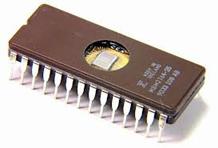
Here is an OTP. No window.
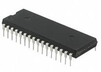
When they came out with single-chip microprocessors that had everything on the chip (called microcontrollers) they generally used either EPROMs or Masked ROMs on the chip for program memory. They had two versions of EPROMs. One had a window so you could erase it (use it for development) and the other had no window (OTP) for production.
The PIC16C57-RCI/P used in my Ruud Control Board uses an OTP EPROM.
Here is what is important.
The bits are stored as charges in a floating gate isolated by two oxide layers. No oxide layer is a perfect insulator. Eventually the charges will leak away, and there goes your program/data. The technical term is “Bit Rot.” (And since programming the memory causes some stress to the part it can only undergo a limited number of write cycles. Then it wears out. It’s called “Wear Out.”)
How long does it take for Bit Rot to set in?
It depends on the operating voltage of the part and its temperature history. The higher the voltage and the higher the temperature history of the part the sooner it starts to happen. EPROM manufacturers used to discuss this problem and provide data and charts. They stopped providing this information decades ago. I remember that 20 years was reasonable for the 27C512s which I used in several of the Atari Coin-Op games that I designed the hardware for. I am going here on my own memory (which is also subject to Bit Rot).
Since my furnace was manufactured in 1995, in 2012 it was about 17 years old. And the PIC16C57 was also about 17 years old. And it had lived some of its life at temperatures around 120 degrees.
Had Bit Rot set in, in my PIC16C57? Is that why it stopped working properly? Is that why the Diagnostic LED never flashes an Error Code?
Probably not. If Bit Rot had set in then it is likely that the program would have totally crashed.
Still, it was probably a good idea to replace the Control Board.
My other furnace is in the garage so its temperature history is much lower. How old is your furnace and where is it?
If you have gotten this far there is something else you should know.
You know those Flash Memory Cards and USB Memory sticks that are everywhere nowadays and you may have noticed the increasing use of Solid State Drives (SSDs) ?
The underlying technology in these memories is:
{Drum Roll}
EPROM Technology!
The bits are stored as charges in a floating gate isolated by two oxide layers.
The difference are:
1. The memories are electrically erasable, and they are erasable in small blocks. You don’t erase the entire memory in order to write one new byte.
2. The memories contain a controller to spread the memory write cycles out over the entire memory so you are not always writing to the same blocks. It’s called “Load Leveling.” If the capacity of your flash memory is going down it means that blocks are wearing out and being mapped out of use.
What this means is that you should not use Flash Memory Cards, USB Memory Drives, and SSDs to archive data.
Eventually they will all suffer from Bit Rot.
What media should you use to archive data?
1. For cost and storage capacity it is hard to beat Hard Disk Drives. However, HDDs are mechanical and don’t last forever. What happens, though, is that HDDs get filled up and people copy them to new and bigger HDDs. When you do that be sure to copy all of the files that you want to keep. My first HDD was 60 Mbytes, cost several hundred dollars, and came with its own disk controller card. (It was before the IDE interface was invented.) My standard HDD now is 1 Terabyte and costs around $50. A Terabyte is 1000 Gigabytes and a Gigabyte is 1,000 Megabytes so a Terabyte is 1 million Megabytes.
The other problem with HDDs is that they can be wiped out by an Electromagnetic Pulse (EMP). EMPs are produced by nuclear devices, even small ones. A small nuclear device exploded 100 miles above Kansas would bring down the Eastern Grid, the Western Grid, and the Texas Grid. The transformers in these 750 KV lines are already operating at or slightly above their rated capacity. The added current induced by an EMP would burn them out. The transformers are not stock items and are only built to order. You might think we would have had a bunch of them built ahead of time and stored them in a warehouse (or warehouses) but Congress says, “No, we can’t afford it.” http://securethegrid.com/the-basics-of-grid-security/
If your HDD is anywhere near an EMP it will be destroyed unless it is in a Faraday Cage (https://en.wikipedia.org/wiki/Faraday_cage) or deep enough underground.
EMPs are also produced by a solar event called a Coronal Mass Ejection (CME). https://en.wikipedia.org/wiki/Coronal_mass_ejection
A CME hit the Earth in 1859 and burned out telegraph lines all over North America. The reason it didn’t burn out anything else is because there wasn’t anything else. No power lines, no telephone lines, no phonographs, no radios, no televisions, no computers, no cell phones, no ipods. Nothing. (The event of 1859 is known as the Carrington Event https://en.wikipedia.org/wiki/Solar_storm_of_1859)
Unfortunately, a very large CME will also blow away our atmosphere. {Gasp!}
2. Optical discs like CDs and DVDs should survive an EMP. Unfortunately the storage capacity of optical discs has not kept pace with HDDs. A CD is good for only 650 MBytes. A standard DVD is 4.3 GBytes. A Blu-Ray DVD is 25 GBytes (50 GBytes for dual layer). At 50 GBytes per disc it would take 20 Blu-Ray discs to equal a 1 Terabyte HDD.
Sony and Panasonic have announced a new optical disc system that can store 1.5 Terabytes per disc and will keep the data for 50 years. http://panasonic.net/avc/archiver
I hope they are successful and it becomes cheap enough for consumers to buy.
3. For long term storage you cannot beat the old technology.
a. Engraving symbols in stone. It is low bandwidth and low storage density but storage lifetime can be several thousand years.
b. Writing ink on animal skins (like sheepskins). Also low bandwidth and low density. Storage lifetime can be a thousand years if properly stored.
c. Printing on pulp paper. Better bandwidth and density than stone and animal skins. Can be machine written (a computer printer). The storage lifetime can be several hundred years (maybe more) if properly stored but only if high quality (acid-free) paper is used.
Suppose all of our stored data were wiped out (and us, too).
Ten thousand years from now when alien archeologists are visiting our planet the only record of our civilization will be what they find in our landfills.
J. I invent a better flame sensing system
I invented a better flame sensing system, reduced it to practice by building it, and filed a patent application.
|
ABSTRACT OF THE DISCLOSURE This invention relates to the field of sensing flames in equipment such as gas furnaces by using the electrical properties of flames. In a first group of embodiments flame rectification is used to cause distortion of a signal having a selected waveform. A harmonic of the distorted waveform is detected thereby providing flame proof. In a second group of embodiments flame rectification is used as a mixer to cause two signals having selected waveforms to produce sum and difference signals. The sum and/or difference signals are detected thereby providing flame proof.
|
For the published patent application click here.
Assuming I get the patent will the World:
1. Beat a path to my door?
2. Beat me up and steal it?
3. Ignore me?
I’ll let you know.
K. About Thermostats
The Summer after my furnace was fixed I wanted to use my air conditioner. It started up and then promptly shut down. This time the problem seemed to be the thermostat and occurred when the set point for cooling was more than 2 degrees below the room temperature.
My old thermostat was a Lux 9000. It operates solely on its batteries because it does not use the 24VAC from the furnace. It can’t. There is no “C” terminal. (The “C” terminal is 24VAC_Common.) On the other hand the drain on the battery is extremely small, about 6.5 uA. I liked the Lux 9000 because it explicitly told you how long the blower had been running. This made it easy to determine when to change the filters. I wish they still made the Lux 9000, but with a “C” Terminal.
When I put in a new thermostat I learned something interesting about thermostats.
Some history.
Before there were electronic thermostats the thermostats were mechanical devices that used a bimetallic strip made of two dissimilar metals that expand and contract as different rates as the temperature changes.. An early patent that teaches the use of a bimetallic strip is U.S. Patent No. 281,884 Electric Tele-Thermoscope issued July 24, 1883 to Warren S. Johnson. The two dissimilar metal strips are wound together in a spiral with the inside end fixed and the outside end controlling a beam lever. Under each contact point of the beam lever is a small cup of mercury. When the temperature is below the set point one end of the beam contacts its pool of mercury and the contact on the other end of the beam is lifted out of its mercury pool. When the temperature is above the set point the beam lever pivots reversing which pool of mercury is in contact with its respective beam lever contact. For the Johnson patent click here. (I cleaned up the USPTO’s patent by straightening the pages and removing their scanning artifacts.) Warren S. Johnson was the Johnson in Johnson Controls (http://www.johnsoncontrols.com/content/us/en/about/our_history/warren_s__johnson.html)
This evolved so that instead of two open cups of mercury the mercury was in a sealed capsule with two electrodes. As before, the bimetallic strip is wound in a spiral with the inside fixed. However, instead of the open cups of mercury a mercury capsule is mounted at the free end of the spiral. The expansion and contraction of the bimetallic strip around the set point causes the mercury capsule to tilt one way or the other. One way causes the mercury to wet the electrodes and complete the circuit. The other way draws the mercury away from the electrodes opening the circuit. The mercury capsule is elongated to produce hysteresis. An example of a mercury switch thermostat is U.S. Patent 1,822,605 Mercury switch thermostat issued September 8, 1931 to Teeple. Click here. It should be appreciated that thermostats with mercury must be installed perfectly level or the set point will be wrong.
In other mechanical bimetallic strip thermostats the bimetallic strips directly make (or do not make) electrical contact with each other. Hysteresis is provided by a magnet. An example is U.S. Patent 2,129,477 Adjustable metallic thermostat issued September 6, 1938 to Parks. Click here.
These mechanical thermostats require only two wires to turn the furnace on.
|
If you are replacing an old thermostat that has the mercury capsule you need to dispose of it properly. Don’t put it out in the trash. There is a Web site that will tell you where you can bring your old thermostat: www.thermostat-recycle.org
If you have an original Johnson thermostat that still has mercury in the open cups then you should call either the hazmat team or Antiques Roadshow.
|
There was a famous and ubiquitous (and round) mechanical thermostat made by Honeywell. There are probably millions of them still in use. It looks like this one.
Figure 46
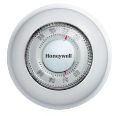
But this one, a Honeywell CT87K, is totally electronic and contains a Lithium coin cell. For the manual click here.
It currently costs $29.68 at Home Depot. That’s a lot to pay for a Retro (but electronic) thermostat. I will examine it in some detail later on.
Mechanical thermostats work by closing two contacts. That’s it.
When the contacts close they tell the furnace to run.
Older furnace controllers used relay logic to control the furnace so the thermostat contacts completed a circuit that turned on a relay that started the process.
Furnace logic is very simple and can be accomplished by a few relays, maybe some with a delay built-in. From https://en.wikipedia.org/wiki/Relay
Timing relays are arranged for an intentional delay in operating their contacts. A very short (a fraction of a second) delay would use a copper disk between the armature and moving blade assembly. Current flowing in the disk maintains magnetic field for a short time, lengthening release time. For a slightly longer (up to a minute) delay, a dashpot is used. A dashpot is a piston filled with fluid that is allowed to escape slowly; both air-filled and oil-filled dashpots are used. The time period can be varied by increasing or decreasing the flow rate.
Not long ago relay logic was used to control elevators. And a long time ago (but within my lifetime) the phone system was run by relays and relay logic.
Back to furnaces.
A mechanical thermostat only needs two wires to control the furnace. The transformer is in the furnace and the relay is in the furnace controller.
Figure 47
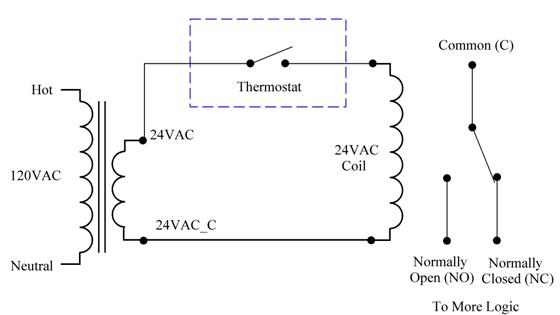
If you want to be able to turn just the fan on, it takes only one more wire. The fan switch uses the 24VAC wire that already goes to the thermostat and it turns on its own relay.
If you have central air conditioning that’s one more wire.
Since mechanical thermostats didn’t use any power themselves there was no reason to run a wire for 24VAC_Common, so installers didn’t.
Then thermostats went electronic.
Nowadays, although there are still mechanical thermostats most thermostats are electronic and need power to operate. An example of an early patent for an electronic thermostat is U.S. Patent 3,942,718 Electronic thermostat issued March 9, 1976 to Palmieri. Click here. This patent does not show where it gets its power from but since it uses discrete logic it is unlikely that the power came from batteries. When the patent application was filed in 1973 there were no microcontrollers, and microprocessors required considerable support circuitry, all of which required more power than was practical to get from batteries for long term use. Therefore, this thermostat would have required external power.
An example of an early patent for a User programmable thermostat is U.S. Patent 4,442,972 Electrically controlled programmable digital thermostat and method for regulating the operation of multistage heating and cooling systems issued April 17, 1984 Sahay, et al. Click here. This patent also required external power. See Figure 5 element 35. It is the furnace transformer.
Since thermostats using the technology taught by both ‘718 and ‘972 would have required external power (such as furnace power) the sales of these thermostats would have generally been limited to new construction and to homeowners willing to install (or have installed) a new cable from the furnace to the thermostat.
Nowadays with the availability of very low power microcontrollers a thermostat may operate solely from its batteries. Some thermostats are designed so that the batteries may last for several years before they need to be replaced. Some thermostats may need its batteries replaced in as little as a year. If the batteries die the furnace will not work and the home’s residents may wake up in the morning to a very cold house. If the residents are away at the time the failure of the furnace to operate may result in frozen and burst water pipes.
Some thermostats augment battery power by the process known as Power Stealing. In Power Stealing the thermostat operates on a small leakage current through the furnace controller input.
Here is how it works.
A relay requires a minimum amount of current to pull-in. Below that current it will not pull-in. So you can use a resistor (or a transformer) across the thermostat switch to allow a current to flow through the relay that will not pull-in the relay. Then you use the voltage developed across the resistor (or transformer) to either charge a large capacitor or recharge a battery.
Figure 48
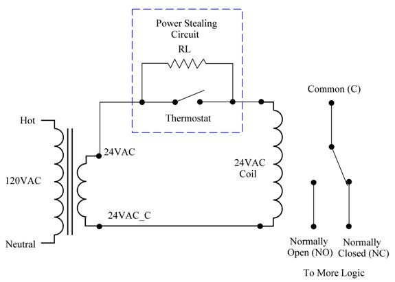
You will probably want to run your thermostat circuitry from DC.
Figure 49
The caveats are:
a. The current you steal cannot be large enough to pull in the relay.
b. Relays also have a drop-out current which is less than the pull-in current. Once a relay has pulled in, it takes less current to keep it pulled in, so the current you can steal has to be less than the drop-out current.
c. Once the thermostat has closed its contacts (a Call For Heat) there is no power available to be stolen. Therefore you need a battery or very large capacitor to operate the thermostat for as long as the furnace is running. How long is that? Ten minutes? An hour? Four hours?
An early patent that teaches Power Stealing is U.S. Patent 4,211,362 Smoke detecting timer controlled thermostat issued July 8, 1980 to Johnson. Click here.
Claim 2:
2. A thermostat as described in claim 1 wherein said thermostat is powered by a small leakage current-flow from said power source through said heat exchanger device during off states of said heat exchanger device, said thermostat including a battery means for supplying operating power to said thermostat when full power is allowed to flow to said heat exchanger device, said thermostat including a power supply circuit means for limiting the current and regulating the voltage upon which said thermostat operates.
Look at Figure 1. This was an analog thermostat except for the digital display.
You should also see U.S. Patent 4,193,006 Multi-stage controller issued March 11, 1980 to Kabat, et al. Click here. Figure 2 shows a digital thermostat that uses discrete logic. No microcontroller. Not even a computer.
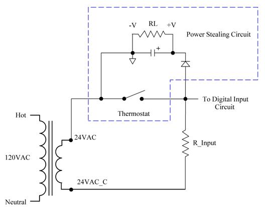
Unless you have a really old furnace controller it probably won’t use relay logic. The inputs will be digital. The digital inputs will be relatively high impedance. If you design furnace controllers and you want them to work with power-stealing thermostats you have to provide an input resistor.
If you design furnace controllers what size R_Input resistor should you use, and if you design thermostats what size R_Input resistor should you assume is being used?
Bear in mind that when the thermostat closes you will have the full 24VAC across your resistor and
Power = V2 / R
The Rudd Furnace Controller uses two 100 Ohm, 5 Watt Resistors.
Figure 50
Power = V2 / R = 24*24/200 = 2.88 Watts
Each Resistor is a 5 Watt resistor, which gives plenty of margin for heat dissipation.
Other boards don’t use 200 Ohms. I have seen several boards (newer than this one) that use 1K on all the inputs.
If the thermostat has a separate switch for controlling the Fan (Blower) you can steal its power, too. The Fan switch will have two positions: Auto and Manual.
In the Auto position the furnace controller controls the blower. In the Manual position the Blower runs continuously. What if you have the Fan switch on Manual? If the thermostat is smart it will know that when it issues a Call For Heat the furnace controller will control the blower so it doesn’t have to, so it can steal power from the Fan circuit.
If the thermostat also controls an air conditioner it is a good bet that the furnace and the air conditioner won’t both be on at the same time. You can always steal power from one or the other.
If the thermostat can get enough stolen power then the only time you need battery power is when the furnace power is off (like during a power failure). Even then the battery is needed only to keep the clock running and remember the settings. And if the microcontroller has some non-volatile memory it can write to, then the battery is only needed to run the clock.
But what if you have stolen power from all of the available sources (Heat, Fan, and Cool) and it is still not enough to run the thermostat? Then you will be using battery power.
And even if the thermostat uses rechargeable batteries (and it probably doesn’t) batteries have a finite lifetime. Rechargeable batteries can only be recharged a limited number of times. And all batteries have a self-discharge rate. Eventually they will die even if they are not being used.
I will now theorize that:
a. Once the manufacturers produced electronic thermostats that work by Power Stealing they saw no reason to design them to also run on the 24VAC from the furnace.
b. Then, when low power circuitry became available there was less reason to run on 24VAC from the furnace or to use Power Stealing. Just run them on the batteries.
Many of today’s thermostats run solely on the batteries.
For example:
a. My old Lux 9000 runs solely on the batteries. However, the unit uses two AA batteries and draws only 6.5 uA. That would allow the batteries to last for several years.
b. The Honeywell RTH221B is an electronic 7-day programmable thermostat that also does cooling. (The RTH2300 version has a backlight.) Click here. It uses two AAA batteries. It does not use Power Stealing. And there is no “C” terminal.
Figure 51
I tested one. The nominal battery drain is 40 uA.
While that is much more than the Lux 9000 it is still very small. The Honeywell unit uses a Texas Instruments M430F413 microcontroller. I suspect that the Lux 9000 uses a custom integrated circuit designed using the techniques used in making digital watches. (If the Lux 9000 was installed when my house was built, then it was made sometime in or before 1995.)
I tested it in my test fixture. The battery drain does not change when the control board being tested has power. Therefore the thermostat does not use Power Stealing.
There is something curious about the Honeywell RTH221B.
Figure 52
There is a label next to a terminal on the PC board that says “C”. That is the terminal in the drawing that says “not used.” When I tested it in my test fixture the battery current did not change. Therefore, it doesn’t go anywhere on the PC Board. (Boooh.)
The relatively high current drain, the lack of Power Stealing, and the lack of a “C” Terminal explains why Honeywell says to replace the batteries once a year.
But the Honeywell RTH221B is only $19.88 at Home Depot.
Let’s look at the Honeywell CT87K. This is the Retro Round Dial thermostat that used to be totally mechanical but is now electronic. But it is still round.
Figure 53
Here is the circuit board.
Figure 54 - CT87K Top

Figure 55 - CT87K Bottom
It cannot run on furnace power but it does do Power Stealing (about 0.7mA when there is no Call For Heat). The Power Stealing uses only the negative half-cycles. That makes sense. By now all of the furnace control boards are solid state and the inputs use only the positive half-cycles. Using only the negative half-cycles for Power Stealing makes it unlikely that the furnace control board will interpret it as a valid input. This has ramifications for the use of Polarity Splitting to be discussed later.
It has a CR2450 Lithium coin cell which is 3V and has an amazing 620mAhr capacity. That compares favorably to two AAA alkaline batteries which are rated for 1,000mAhrs.
The microcontroller is an Atmel Mega 48PA AU 1339. (The “1339” might be a lot number or a date code.)
This is an interesting device.
The Power Consumption at 1MHz, 1.8V, 25°C:
Active Mode: 0.2mA
Power-down Mode: 0.1μA
Power-save Mode: 0.75μA (Including 32kHz RTC)
The active mode (0.2mA = 200uA) looks large but it is likely that it has been programmed to spend most of its time sleeping and only wakes up periodically, maybe for 1ms every second. (One ms is an eternity for both microcontrollers and androids.)
The Power-save Mode is amazing. Just 0.75uA.
Earlier I complained that no one tells you about the retention time for their EPROMs and EPROM-based devices anymore.
Well, Atmel does.
This is from the Datasheet Summary:
High Endurance Non-volatile Memory Segments
4/8/16/32KBytes of In-System Self-Programmable Flash program memory
256/512/512/1KBytes EEPROM
512/1K/1K/2KBytes Internal SRAM
Write/Erase Cycles: 10,000 Flash/100,000 EEPROM
Data retention: 20 years at 85°C/100 years at 25°C(1)
Let me repeat the last part. Data retention is expected to be 20 years at 85°C (185°F) or 100 years at 25°C (77°F). These are very impressive numbers, and I expect that my thermostat will spend more of its lifetime at 77°F than it will at 185°F. (Note that Atmel’s numbers are projected numbers that would be based on the established practice of doing some testing and some calculations.)
For Atmel’s Datasheet Summary click here.
The board has a 1,000 uF electrolytic and a device marked “473 ▌5.5V E7”. It doesn’t have a manufacturer’s name on it unless “ ▌” is a symbol. I believe it is a 47,000uF supercapacitor.
Figure 56
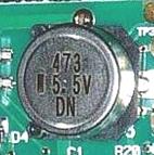
This is a 10,000uF Supercapacitor made by Kemet.
http://www.kemet.com/Lists/ProductCatalog/Attachments/408/KEM_S6011_FC.pdf
Figure 57
Supercapacitors are generally used to provide backup power to a low current device. This would help the microcontroller ride out the time during a Call For Heat when there is no Power Stealing.
The next part to consider is the relay that is used to provide the closed contacts to run the furnace. The relay is an Omron G6SK-2F-H.
Figure 58
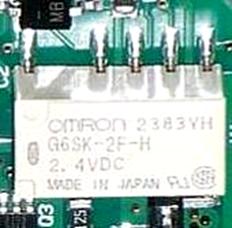
This is a latching relay. This latching relay has two coils. You provide a pulse to one coil and it turns the relay on, and it stays on (latched) until you provide a pulse to the other coil which turns it off. When used to control a furnace you have to make sure the controller doesn’t crash with the relay latched. I think Honeywell has done that with the low power Atmel microcontroller, the Lithium coin cell, and the supercapacitor.
The Honeywell CT87K is basically a 2-wire thermostat. There is no Off switch. There is no Fan Switch (Auto/On). Some people like to run the Fan (Blower) to circulate the air when the furnace is not on. Well, not with this one.
There is a third terminal labeled “Y”.
Figure 59
The “Y” terminal usually means “Call For Cooling.” Not here. Here it is for a hot water heat-only system. (You probably wouldn’t put a heat-only thermostat on a system that has an air conditioner anyway.)
There was probably an engineering design decision that Honeywell made. In Fan Auto mode the furnace controller controls the fan and the Fan Input is not used. Since there is no Fan switch they could have used the Fan Input for Power Stealing so there would be Power Stealing all the time, or at least whenever the furnace has power. (When the furnace doesn’t have power it doesn’t matter if the thermostat is working.) In a strictly 2-wire system there would not be a wire for the Fan switch so they would have needed to design the thermostat exactly the way they did anyway, with a low power microcontroller, a supercapacitor, and a latching relay.
The CT87K has option switches for setting the Cycle Rate.
Figure 60
The Cycle Rate is really the Temperature Swing, which is the temperature hysteresis. A small temperature swing (like 0.25°F) means that the furnace will cycle on and off frequently but your house will maintain a temperature within narrow limits. A large temperature swing (like 2°F) means your furnace will cycle less frequently but the temperature in your house will also vary by 2°F. It would be nice if Honeywell came out and said this, and said what the temperature swing is for the different options. This also goes for all the other thermostat manufacturers who do not make this matter clear.
I have not investigated the accuracy of the dial used to set the temperature.
The battery should last at least to its Shelf Life (about 5 years) and probably longer. The thermostat is not designed to make the battery replaceable. This YouTube video shows how to replace the battery: https://www.youtube.com/watch?v=6VKowLXfERo
Basically, working from the inside you use a flat-blade screwdriver to urge some plastic tabs to move a little. This allows you to remove the outer shell which allows you to remove the pc board. The battery is on the front which is otherwise not accessible. When you put it back together you have to take care to properly position the plastic arm that connects the position sensor in the middle of the board to the notch in the rotating dial. (The notch is not easy to see.)
All in all I think the Honeywell T87K is a superbly engineered thermostat if you need a 2-wire thermostat for heat-only.
Honeywell makes a version that does Heating and Cooling, and has a Fan switch. This is the CT87N.
Figure 61 CT87N
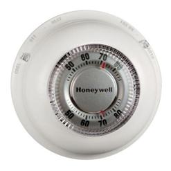
The circuit boards are the same. They don’t need an additional relay for Cooling because they use the mechanical Heat/Cool switch on the base to reroute the relay switch between W (Heat) and Y (Cooling) as well as to tell the microcontroller of the Heat/Cool choice. As with the CT87K the Power Stealing uses only the negative half-cycles. However, because the single relay is mechanically switched between Heat and Cool the Power-Stealing goes with it. When it is on Heat the Power Stealing steals negative half-cycles from Heat input. When it is on Cool it steals negative half-cycles for, the Cool input. This has ramifications for the use of Polarity Splitting to be discussed later.
Figure 62 - CT87N Top
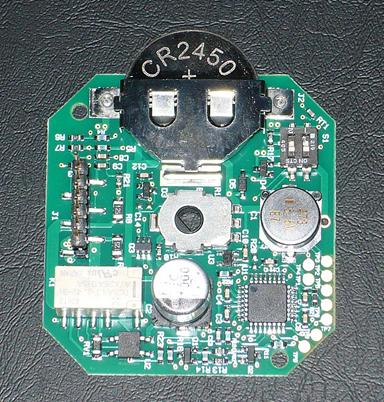
The bottom of the CT87N is stamped: ETL01.
Figure 63 - CT87N Bottom
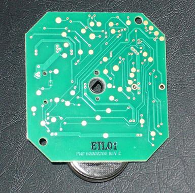
You can see a number of large pads on the board. No doubt they are used for testing and to program the microcontroller. That way you can build a bunch of boards and the last step is to decide which product you are going to use it in. You can wait to make that decision until you start the production run.
The microcontrollers for the CT87N and CT87K are programmed differently because, at the very least, the CT87N needs to see the Heat switch and the CT87K doesn’t. It is always in Heat.
The CT87K is currently $29.68 at Home Depot while the CT87N is a pricey(er) $39.88 .
http://www.homedepot.com/p/Honeywell-Round-Mechanical-Thermostat-Heat-Only-CT87K/100476730
http://www.homedepot.com/p/Honeywell-Round-Heat-Cool-Thermostat-CT87N/202219050
There is someone who still makes a completely mechanical thermostat. The Lux BB101141SA appears to be purely mechanical with no batteries (and is square). Click here. It currently costs $13.20 at Home Depot.
Finally, some thermostats that can use furnace power
I looked at the Lux TX500U Programmable Thermostat. Click here. It can run on batteries or on furnace power. Finally, a thermostat with a “C” terminal. (It does not appear to have power stealing.)
Figure 64
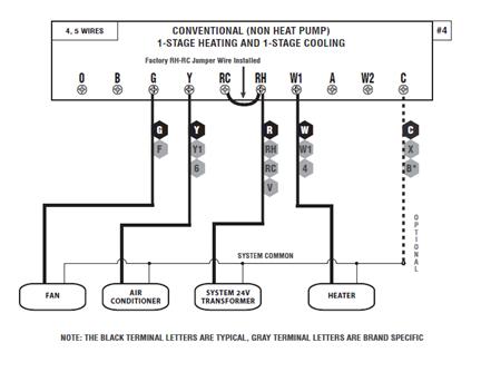
It’s currently $27.99 at Home Depot. http://www.homedepot.com/p/Lux-5-2-Day-Universal-Application-Programmable-Thermostat-LTX500U-A04/204356308
Do not confuse this with the Lux TX500E which does not have a “C” Terminal and runs on battery only.
I also looked at (and bought) a White Rodgers P200. It is currently $26.05 at Home Depot: http://www.homedepot.com/p/White-Rodgers-P200-5-1-1-Day-Single-Stage-Programmable-Thermostat-P200/204804198?MERCH=REC-_-nosearch2_rr-_-NA-_-204804198-_-N
Figure 65
It can be run on furnace power or from its two AA batteries.
Look, it has a “C” Terminal.
Figure 66
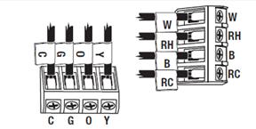
For the manual click here.
The manual doesn’t explain why you should hook up the C Terminal so I will.
If you hook up the wire to the C Terminal you will be running the thermostat on furnace power assuming the other end of the wire is connected at the furnace to its C terminal.
The batteries will last much longer. And if the batteries die you can still run the furnace.
Of course, you can still run it solely on batteries.
When I ran the thermostat solely on the batteries I measured a typical current of 15 uA. With a self-discharge rate of AAs of about 4.8 uA I would expect a pair of new AA batteries to last 63,000 hours, which is about 7.2 years. This time will be shorter depending on how often the furnace (or air conditioning) starts. Starting and stopping draws more current.
When I ran the thermostat on furnace power I measured a current of 1.5 uA. With a self-discharge rate of AAs of about 4.8 uA I would expect a pair of new AA batteries to last 198,000 hours, which is 22.6 years. Again, this time will be shorter depending on how often the furnace (or air conditioning) starts.
Why is that?
The display backlight operates solely on the batteries. It does not run on furnace power. And since the backlight is so dim as to be worthless I wonder why they even bothered to have a backlight.
But if the batteries really do last 22.6 years you may want to put instructions in your Will for your children to replace the batteries.
The White Rodgers P200 has two more advantages and one more disadvantage.
One of the advantages is that the circuit board is mounted on the wall plate.
Figure 67
When the circuit board is mounted on the cover plate (which everyone else seems to do) there has to be a connector (generally a long pin connector) that has to be engaged.
When you pull the cover plate, such as to replace the batteries, your furnace doesn’t work. If you are replacing the batteries you will probably lose at least the clock time and maybe the settings as well.`
With the P200, as long as you have furnace power you could replace the batteries and not lose the clock or the settings.
The other advantage of the P200 is that the faceplate is easy to remove. With other thermostats (especially Honeywell’s) removing the faceplate requires so much force that I am always afraid that I will pull the wall plate out of the wall.
The other disadvantage of the P200 is that they use connector blocks with really crappy screws. They are nominally Phillips head screws (with added slots for a flathead screwdriver) but none of my Phillips head screwdrivers will properly engage them. Using a small flat blade screwdriver I was able to turn the screws but only with great difficulty, made worse because the slots are shallow and the screws were very tight.
I considered the following possibilities for the screws:
1. The punch was not stamped into the screw head far enough.
2. The punch was worn and failed to produce sharp shoulders.
3. The screws were over-tightened during the assembly of the block (or the assembly of the thermostat) and stripped out the Drive (the recessed part that the Phillips screwdriver fits into).
I talked to White Rodgers Customer Service and they sent me a new thermostat (thank you, Shiela). Unfortunately the new one had the same deficiencies as the old one.
The P200 could have been a great thermostat. But if you have a high aggravation threshold to deal with the crappy screws in the connection block, and you don’t care about the backlight, it is still a good thermostat.
WiFi
Honeywell does make some thermostats that run from furnace power. They are their WiFi thermostats and they have to run on furnace power. WiFi is power-hungry.
Look at the Honeywell RTH6580WF. For the installation manual click here.
This is from the instructions:
|
1.7 Connect wires
1.7a Starting with the C Wire, match the sticky tag on the wire to the terminal labels.
Important! C wire is required and is the primary power source. Without a C wire, your thermostat will not power up.
View the Alternate Wiring videos at wifithermostat.com/videos
|
Here is an active link to wifithermostats.com/videos: www.wifithermostat.com/videos
The video tells you to use an unused wire in the cable. (You also have to connect the unused end of the unused wire to the “C” terminal on the furnace control board.)
What if you don’t have an unused wire in the cable and you don’t want to install a new cable from your furnace to your new thermostat?
They make a sensible suggestion. You can use the “G” wire. The “G” wire is the wire used for the Auto/Fan.
1. Turn off the power to the furnace.
2. Connect the wire formerly known as “G” to the C Terminal on the thermostat.
3. Go to the furnace Control Board and remove the wire going to the G Terminal and connect it to the Control Board’s C Terminal.
4. Put everything back together and restore power to the furnace.
When you do this you will no longer be able to manually turn the blower on to circulate the air when the furnace (or air conditioner) is off. However, the blower is turned on by the furnace Control Board when you run the furnace or the air conditioner and it will continue to do that.
If you rarely (or never) turn the blower on manually then this is a good solution.
You can also do this (hijack the G Wire) with a regular thermostat that you want to run on furnace power when:
1. It is a thermostat that can be run on furnace power; and
2. You won’t miss being able to run the blower manually.
There is another way. This way preserves the ability to use Auto/Fan.
Here is the standard wiring for a system where the thermostat controls Heat, Cool, and Auto/Fan and only has four wires so the thermostat does not get furnace power.
Figure 68
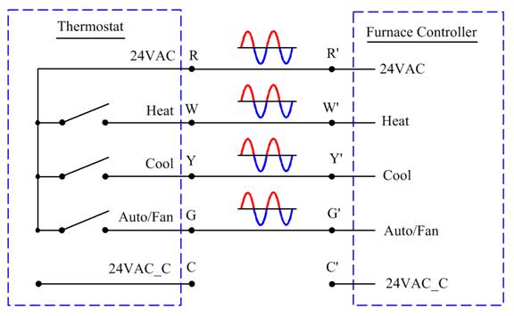
We will start with a simpler a three-wire thermostat that controls Heat and Auto/Fan. It does not get furnace power and must use batteries and maybe Power Stealing.
Figure 69
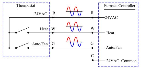
The relay (or switch) contacts in the thermostat complete circuits from the 24VAC furnace transformer.
Here is how to use Polarity Splitting in a three-wire system to add furnace power to the thermostat. This controls Heat and Auto/Fan.
Figure 70
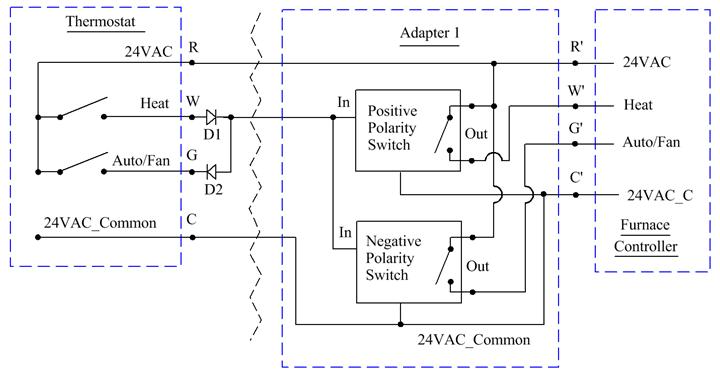
We will separate the positive and negative parts of the 24VAC with diodes at the thermostat. The Call for Heat will select only the positive half-waves while the Auto/Fan will select only the negative half-waves. These positive and negative half-waves are then combined onto one wire going from the thermostat to the furnace. An adapter is located at the furnace that uses more diodes to separate the positive and negative half-waves.
The positive half-waves are filtered to provide a positive voltage to control a first DC relay. The contacts of this first DC relay provide the Call for Heat input to the furnace controller. The negative half-waves are filtered to provide a negative voltage to control a second DC relay. The contacts of this second DC relay provide the Auto/Fan input to the furnace controller.
The contacts on these relays will spoof the Call for Heat and Auto/Fan to the furnace Control Board.
This is how the Polarity Switches work.
Figure 71
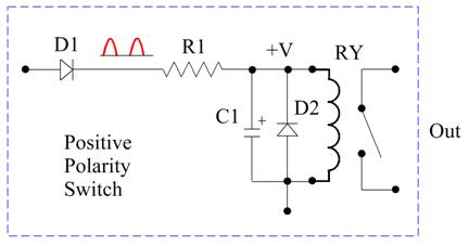
Figure 72
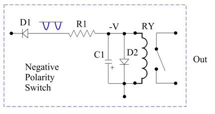
For each Polarity Switch: D1 and D2 are 1N4002; R is 200Ohm 1/2W; Relays are Omron G5LE-1A4 DC24; C is 100uF 50V.
Using Polarity Splitting in a three-wire system to add furnace power to the thermostat, this controls Heat and Cool, but no Auto/Fan.
Figure 73
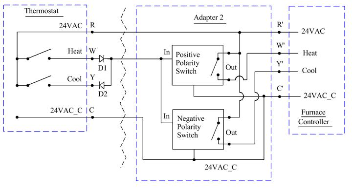
Using Polarity Splitting in a three-wire system to add furnace power to the thermostat, this controls Cool and Auto/Fan.
Figure 74
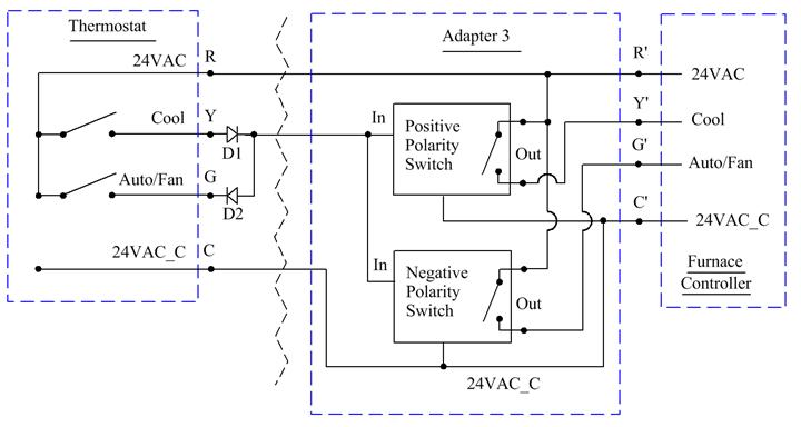
And now we will go back to the four-wire system and use Polarity Splitting to add furnace power to the thermostat. This controls Heat, Cool and Auto/Fan.
Figure 75
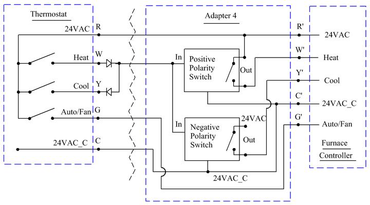
It would be nice to have some indicators at the furnace to show what the thermostat is calling for.
Figure 76
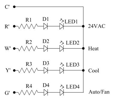
D1 – D4 are 1N4002
For Ultrabright LEDs R1 – R4 are 100K, 1/4W
The Adapter Board (which may include the LEDs) should be in a protective plastic box located either inside the furnace near the Control Board (in the blower compartment) or outside (but near) the furnace.
If you install it outside the furnace you will be able to see the LEDs that show 24VAC Power, Call for Heat, Call for Cooling, and Auto/Fan.
You can use this technique if you have only two wires from the furnace to the thermostat. Although it requires that the thermostat operate on batteries it gives you two functions.
Here is a two-wire system that uses Polarity Splitting to make two functions instead of one. The thermostat must be battery-powered but can control Heat and Cool.
Figure 77
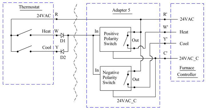
Here is a two-wire system that uses Polarity Splitting to make two functions instead of one. The thermostat must be battery-powered but can control Heat and Auto/Fan.
Figure 78
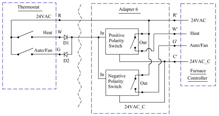
Here is a two-wire system that uses Polarity Splitting to make two functions instead of one. The thermostat must be battery-powered but can control Cool and Auto/Fan.
Figure 79
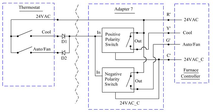
We can use Polarity Splitting to have the Auto/Fan wire perform a second function. Some furnaces need extra controls. Examples are multistage furnaces and hot water heating systems.
Figure 80
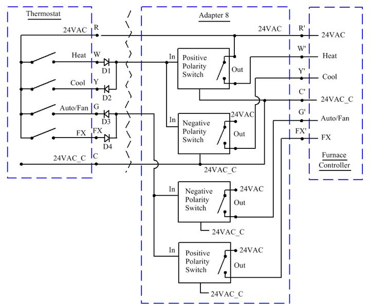
As long as the 24VAC and 24VAC_Common at the thermostat is the same as the ones at the furnace controller, it doesn’t matter where the Polarity Splitter is and where its switch is. In this configuration the Polarity Switch is at the Furnace Controller and the Polarity Splitter is at the thermostat. This allows us to send a signal from the Furnace Controller to the Thermostat.
Figure 81
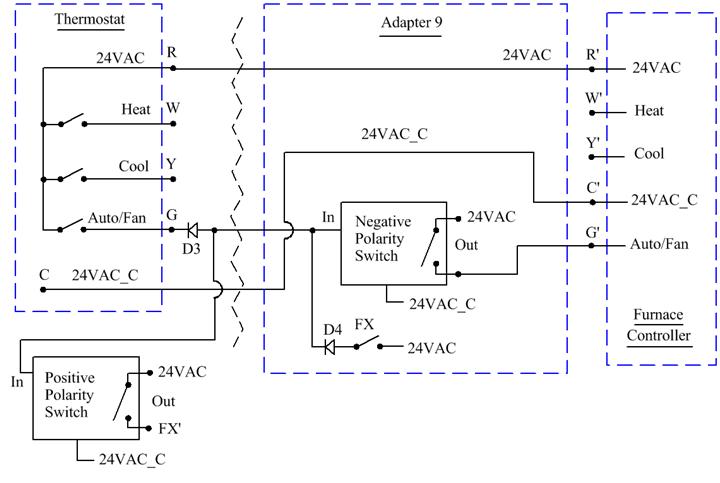
Since this does not use a circuit in the Furnace Controller (which could be
anything) we can use our own circuit. This circuit controls an LED at the
Thermostat so the Polarity Splitter is just Resistor R3, Diode D5, and LED 1.
Figure 82
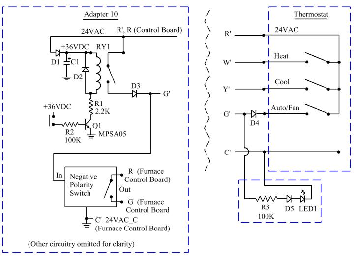
Having the LED at the Thermostat controlled by a pushbutton switch at Furnace Controller might not be very useful. What I want to see at the Thermostat is the status of the Diagnostic LED on the Furnace Control Board. In order to do this without modifying the circuit on the Control Board we will use a phototransistor to look at the Diagnostic LED. It should be possible to sneak two wires out of the Thermostat base. There might even be room in the Thermostat base for R3 and D5. As an alternative we can have the phototransistor look at the Flame Good LED.
Figure 83
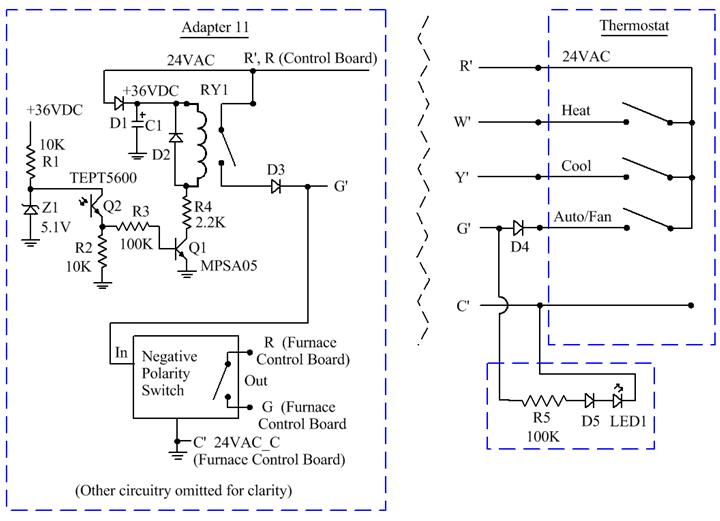
Instead of using a Relay for the Polarity Splitter we can use some transistors. The 2N5401 has a maximum VCE of -150V. The MPSA05 has a maximum VCE of 60V.
Figure 84
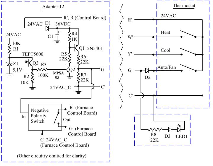
When I built this circuit and tried it with my old (1995) Ruud Control Board the LEDs on the board were too dim. I started by replacing LED 2 (“Good”) on the board with a modern superbright LED. The control board promptly burned it out. There was too much current provided by R40 (4.7K). Since I was committed to making this work I promptly replaced R39, R40, and R41 with 100K resistors. Even with 100K resistors the new LEDs are nice and bright, and the phototransistor has no problem seeing them when they are on.
If the furnace does not have a window in the panel we cannot see the Diagnostic
LED on the Control Board without taking off the panel, and taking off the panel
opens the interlock switch which turns off the furnace. Then you have to hold
in the interlock switch and have the furnace start up again. Suppose it is an
intermittent problem? Then you won’t know what went wrong the first time. So we
will add an LED to the Adapter Board so we can see the state of the Diagnostic
LED without taking the panel off.
Figure 85

As long as we are at it we will add another phototransistor (and associated circuit) so we can also see the state of the Flame Good LED without taking off the furnace panel.
Figure 86
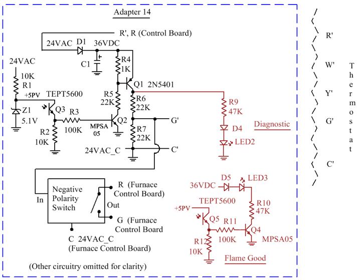
It would be nice to be able to see the state of both the Diagnostic LED and the Flame Good LED at the thermostat. It’s more complicated so I will start with a short review.
A full capability thermostat with furnace power requires five wires. All of the signals go from the thermostat to the furnace controller.
Figure 87
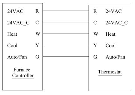
In the previous section we used Polarity Splitting to create a single backchannel from the furnace to the thermostat. If that is all we did, it would still require five wires
Figure 88
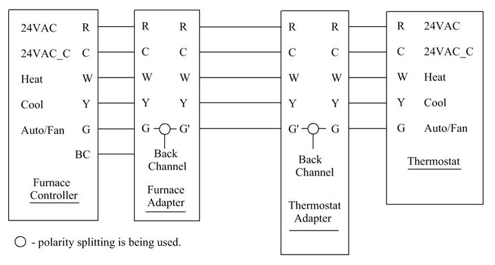
Then we also used Polarity Splitting for the Heat and Cool functions to reduce the number of wires to four.
Figure 89
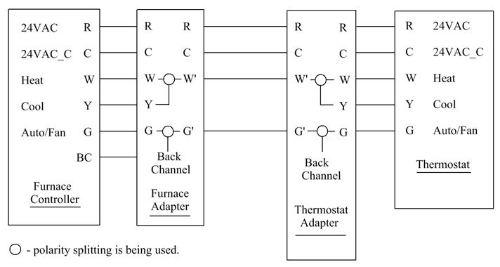
Let’s look at the waveform again.
Figure 90
In the previous section we used the entire positive polarity for the back channel.
We don’t have to. The 60Hz waveform has a period of 16.67ms. We have 8.33ms to play with. (We will square up the positive half-cycle.)
Figure 91
All we need are some timers that are the same at the Furnace Controller and at the Thermostat Controller. We could use analog one-shots but the resistors and capacitors will drift with temperature. We could use some SSI counters but I have decided to use an inexpensive microcontroller, the Texas Instruments MSP430G2211. In quantities of 1,000 it is currently $0.73 at Digikey.
http://www.digikey.com/product-detail/en/MSP430G2211IN14/296-25829-5-ND/2237184
The schematics for Adapter 15 (and then Adapter 16) should be considered as “Proof of Concept” and not production prototypes.
I am posting the code for them. The programs are written in C, compiled with Code Composer 6, and run on the Texas Instruments MSP430 Launchpad. But you should know that:
1. I will not support or answer questions about the code or Code Composer;
2. I will not modify the code for you;
3. I will not send you programmed parts or PC Boards.
I just don’t have time to do any of the above. Please do not ask me to make an exception for you. By the time you read this I will have already moved on to a new and different project.
I am posting the files as html files. You copy the contents into main.c for each Code Composer project.
Adapter 15 - Furnace: main_adapter15_furnace.htm
Adapter 15 - Thermostat: main_adapter15_thermo.htm
Adapter 16 - Both: main_adapter16_both.htm
The programs for the Adapter 16 Furnace hardware and the Adapter 16 Thermostat hardware are almost the same. The difference is taken care of by whether the P1.5 input is grounded or left floating.
I am also posting files that show how to use most of the clock capabilities of the MSP430G2211 (one is for the MSP430G2553). Read the voluminous documentation for the MSP430 series to find out why you would want to use the various clock capabilities.
If you don’t do anything with the Clock, the part will come up using the DCO running at 1MHz or thereabouts.
main_clock1.htm - MSP430G2211 Default DCO (1 MHz) without calibration
main_clock2.htm - MSP430G2211 DCO at 8 MHz, calibrated to 32.768 KHz crystal. Does this after a Reset, does not change the Calibration data in Flash Memory.
main_clock3.htm - MSP430G2211 Uses 32.768 KHz crystal for MCLK
main_clock4.htm - MSP430G2553 DCO at 16 MHz, calibrated to 32.768 KHz crystal. Does this after a Reset, does not change the Calibration data in Flash Memory
main_clock5.htm - MSP430G2211 External Clock Input. Despite the spec, it works up to 16 MHz.
And some more:
main_uart_test.htm - MSP430G2553 Set up the UART at 4800 Baud and send incrementing numbers
main_timer.htm - MSP430G2211 See how TIMER A and interrupts work
Adapter 15
Part 1 consists of the power supply, microcontroller, and a zero-crossing detector. Capacitors C10 and C11 might not be necessary. Pullup resistor R4 is definitely necessary because the internal pullup on the Reset line doesn’t work. The reason for the LM7812 is because the LM1117T has a maximum input of 15Volts.
Figure 92
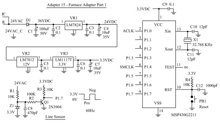
Figure 93
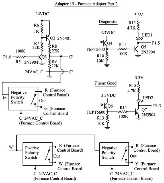
Here is the thermostat adapter. Part 1 of the thermostat adapter is the same as Part 1 of the furnace adapter. Again, capacitors C10 and C11 might not be necessary but pullup resistor R4 is definitely necessary because the internal pullup on the Reset line doesn’t work.
Figure 94
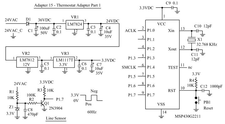
Figure 95
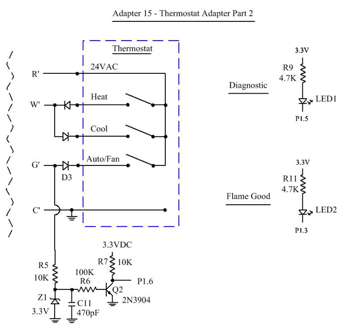
Notes:
I am using a software loop for timing but the DCO doesn’t seem to noticeably drift with temperature. Besides, the timing requirements are very loose. If it is a concern you can:
1. Run the DCO Calibrate function periodically (maybe once a day) but only when the HVAC is off.
2. Don’t use software loops for timing. Use an interrupt running from the 32.768 KHz crystal.
3. Use an external crystal oscillator (at 1MHz or higher) for the clock. (The MSP430G2xxx series does not have the high-frequency XT2 crystal option so you have to have your own oscillator.)
Since we have a microcontroller at each end, we might as well have them communicate with a UART. This gives us furnace power to the thermostat with full thermostat functionality and with full backchannel capability from the furnace, all with only three wires.
The three wires are:
|
24VAC |
R |
|
24VAC_Common |
C |
|
Data Link |
D |
Adapter 16
I am using the MSP430G2553 because it has more I/O pins and a UART. In quantities of 1,000 (at Mouser) it is about $1.12 .
Figure 96
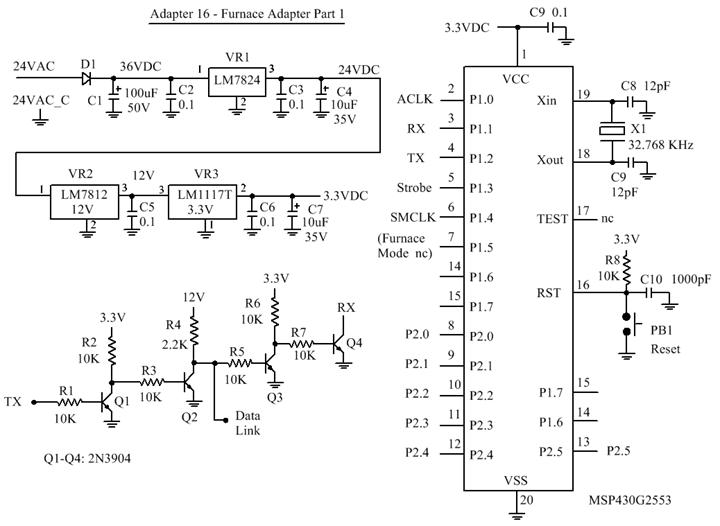
Figure 97
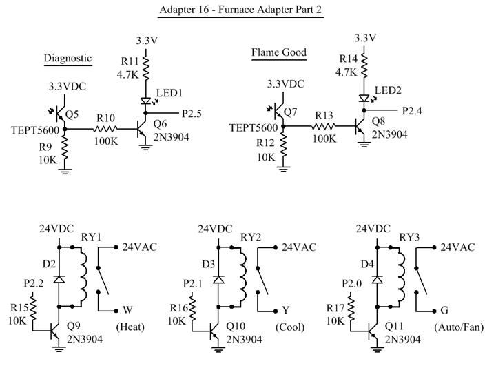
Notes:
1. Oscillator capacitors C8 and C9 seem to be optional.
2. However, pullup resistor R8 is definitely required. Although the MSP430 claims to have an internal pullup resistor on the Reset line, it doesn’t seem to work.
3. Also, you can monitor the 32.768 KHz oscillator on ACLK (P1.0).
I produce the Strobe signal on P1.3 at the beginning of every UART transmission so I can synchronize an oscilloscope to it.
Figure 98
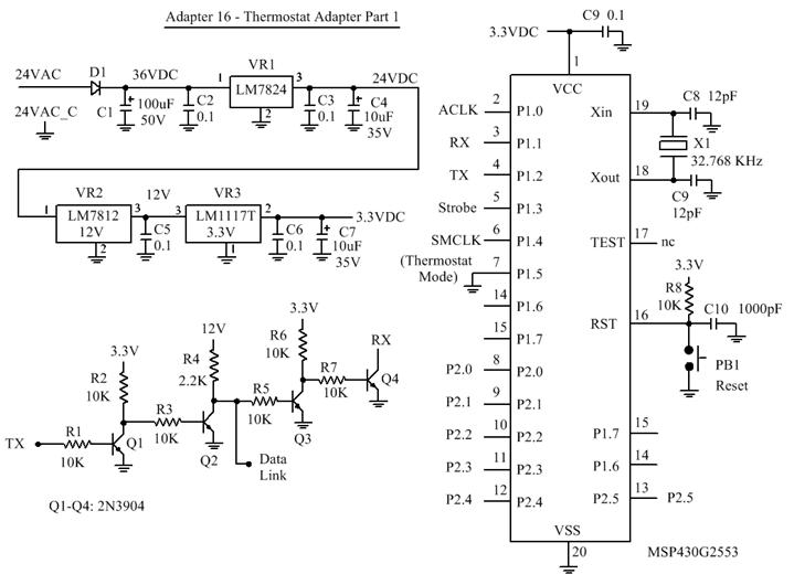
Figure 99
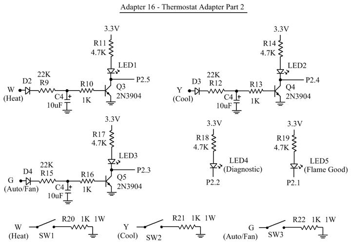
The reason for having SW1, R20, SW2, R21, SW3, and R22 is that some thermostats do power stealing. If the thermostat doesn’t need it then turn the switches off.
I have put these figures all together in a PDF file in landscape orientation. Click here.
I mentioned earlier that the Honeywell CT87N uses (and needs to use) Power Stealing in order to work, and that it uses it on the negative half-cycles of both Heating and Cooling. You can use Adapter 16 as shown. You can use Adapter 15 by adding the 1K resistors to W and Y at the thermostat. On the adapters that do not provide furnace power you have to arrange things so that both Heat and Cool use negative Polarity Splitting. (Fan/Auto can use positive Polarity Splitting.) But, for example, Adapter 5 will not work with the CT87N. Or, you can get a thermostat that does not use Power Stealing.
Future Improvements
The UART runs from the 32.768 KHz crystal so it will not be affected very much by temperature. The software loops for timing are minimal. Nonetheless, the same improvements can be made here as well as for Adapter 15:
1. Run the DCO Calibrate function periodically (maybe once a day) but only when the HVAC is off.
2. Don’t use software loops for timing. Use an interrupt running from the 32.768 KHz crystal.
3. Use an external crystal oscillator (at 1MHz or higher) for the clock. (The MSP430G2xxx series does not have the high-frequency XT2 crystal option so you have to have your own oscillator.)
4. For added robustness require that a number of consecutive commands (like eight) be issued by the thermostat before changing the relays for Heat, Cool, and Auto/Fan from Off to On or On to Off.
5. Instead of dedicating one bit in the UART data for each function (giving only eight functions), assign one of the 256 data combinations to the function. For example: Code 001d for “Turn Heat Relay On; Code 002d for Turn Heat Relay Off. This give 128 functions (for both ON and Off) instead of just eight.
So far we have a system that provide full thermostat functionality, furnace power to the thermostat, and back channels from the furnace to the thermostat using only three wires.
How about doing it with two wires?
1. We could do this using the characteristics of the thermostats. For example, although the Honeywell CT87N requires power-stealing in order for it to work, it only does power-stealing during negative half-cycles. We could use the positive half-cycles to provide power to our thermostat adapter as well as for communications.
2. The thermostats that use furnace power only draw current during positive half-cycles, indicating that they use a half-wave power supply circuit, not full-wave. Thus we could use the negative half-cycles for communications. We wouldn’t even have to go negative. It only has to be less than near-peak.
However, the two systems would be incompatible and we would want the system to work with all standard thermostats.
3. We could use method #2 and then have the thermostat adapter generate its own 24VAC 60Hz for the thermostat.
4. Provide inductive isolation from the 24VAC 60Hz power and use high frequency carriers for communications. Here, high frequency means around 100KHz. It‘s like an old dial-up modem only with higher-frequency carriers.
That is a lot of work for what is very likely a small market. By now, most homes should have at least three wires from the furnace to the thermostat.
Let’s take a step back.
With both Adapter 15 and Adapter 16 we have a microcontroller in the thermostat adapter. We could use it to make our own thermostat.
There are some practical difficulties in doing that.
Honeywell seems to have the lion’s share of the thermostat market. Just go to the thermostat section of Home Depot. The other major players for conventional thermostats are Lux and White Rodgers. Then there are a few others with unfamiliar names. Then there is Nest (now owned by Google) with WiFi thermostats.
Honeywell makes a variety of thermostats at different price points with different features, especially the programmable ones.
You program the programmable thermostats by pressing a few buttons with one hand, holding the instruction manual in the other. You look at the small cryptic screen, then the instruction manual, and you probably go back and forth a few times. (I have a Honeywell security system. Programming it is a real nightmare.)
That is so 20th Century (at least the late 20th Century). If I am going to program the thermostat schedule I want to use a well-designed GUI.
Also, there is an 800 pound gorilla in the room. A dumb 800 pound gorilla. (Ok, my Ruud furnace weighs only 160 pounds but it is still dumb.)
Flashing lights? Please! Most of the science fiction movies of the 1950s showed control panels with knobs, switches, analog meters, and lights. Invariably someone would turn a knob to turn up the power. And, naturally, they would turn it up too far. The meters would pin hard to the right. An alarm would sound (and not a wimpy piezo alarm). And the lights would flash.
This is what I want my gas furnace to do:
1. I want it to perform extensive diagnostics. I want it to monitor things like blower motor current and air pressure in the duct leaving the furnace. This will tell me if the filter is getting clogged or if the blower motor is starting to fail.
I want it to determine whether the appropriate operations have taken place, like did the gas valve open when it was supposed to?
I want it to measure flame quality. Even the crude flame sensor in Section G can infer the quality of the flame since the width of the pulse is determined by the net voltage produced by flame rectification.
I want it to measure the incoming gas pressure and the temperature in the combustion compartment.
I want it to measure the Mains voltage and frequency. Some parts of the controller will need battery backup to do this while other parts (high current parts like the Blower, Gas Valve, and relays) will not. But if you use the technique in Section M(8) your gas furnace will run without Mains power so when there is a power failure you won’t freeze in the dark. You will stay warm in the dark. (Get a flashlight.)
2. I want it to log every startup and shutdown and timestamp it. It can store it in a battery-backed RAM and periodically dump it into flash memory, maybe once a day or once a week. If the furnace malfunctions it should dump the data immediately.
3. I want to be able to access this data without having to go to the furnace (it’s in the attic).
There are a number of ways to do this.
1. Have the furnace talk to the thermostat so I can access the data through the thermostat.
a. Use the three-wire serial link described in Adapter 16.
b. Use two wires from the furnace to the thermostat to provide power for a very secure WiFi thermostat. The furnace needs to have WiFi anyway so I can get the furnace data without going into the attic. However, unless the WiFi thermostat is able to issue furnace commands through WiFi some additional software in the WiFi thermostat would be needed. If the WiFi thermostat is secure enough to accept user commands (and programs) it is secure enough to issue commands to the furnace. If the WiFi isn’t secure enough to issue commands to the furnace then it isn’t secure enough to accept user commands (and programs).
c. You can also make an adapter for an existing dumb furnace so you only need two house wires. All they do is provide power for the WiFi thermostat. The adapter will talk to the WiFi thermostat and look like a regular thermostat to the dumb furnace. After all, it only needs a maximum of three switch closures (Heat, Cool, and Fan.), 24VAC (R Terminal) and 24VAC_Common (C Terminal). That’s five wires in a short cable.
Which would you rather do, pay a furnace Guy for an hour’s work (probably the minimum charge) to install the new thermostat and the adapter or pay him (or an electrician) for two or more hour’s work to install the thermostat and run a new cable to the thermostat? Is it even possible to run a new cable in your house inside the walls?
Since installing the adapter only requires connecting five low-voltage wires to the existing dumb furnace controller many people can do this themselves. Again, unless the WiFi thermostat is able to issue furnace commands through WiFi some additional software in the WiFi thermostat would be needed.
Note that the antenna for the WiFi adapter will be in or on the adapter so the adapter must be located outside the furnace cabinet and connected to the dumb furnace controller by the five wires. Two wires of the existing house cable will be connected to the dumb furnace controller (R Terminal and C Terminal) to send 24VAC to the WiFi thermostat.
2. Since the furnace is going to be very smart and I am going to access it with a WiFi device (such as a Tablet) I don’t need a thermostat. I just need a temperature sensor. This can be done with two wires that send power to the sensor and get a digital temperature measurement back. You use a simple DC circuit for this. It’s easier than if you have to do it over 60Hz power. Also, if you report both temperature and humidity, the furnace controller can determine a comfort index for operating the furnace, air conditioner, or just the blower.
On the other hand, a good Plan B would be to have a basic thermostat (not programmable) so you can take manual control of the system if the WiFi stops working.
Use WiFi Direct so that the furnace WiFi can be used in a home without a wireless router or even a computer. This will allow a Tablet (which is more of a toy than it is a computer) to talk directly to the furnace. See http://www.wi-fi.org/discover-wi-fi/wi-fi-direct . The thermostat is going to look like a tablet anyway (but with a temperature sensor.) With WiFi Direct you can also use a WiFi enabled Smart Phone to talk to the furnace.
There are companies like La Crosse, Acurite and others that make remote temperature sensors. I have several, but the communication link is not secure and the transmitters use batteries. Why don’t they make one with a transmitter that uses a small solar cell to charge a super-capacitor? Naturally, it’s for the ones that are located outdoors. Then they need a way to synchronize receivers to transmitters that does not require removing the “battery” from the transmitter. They should do that anyway. One of my sensors is located where I need a ladder to get to it.
3. You don’t have to proactively monitor your furnace. In a home with a wireless router and an Internet connection your furnace can send you an email if something is going South and needs attention before it fails.
You can have your furnace send an email to your preferred HVAC company to tell them that something is starting to go bad, and they can contact you using email, texting, or even an old fashioned voice phone call.
There are a number of companies that offer VOIP-to-landline service. Your furnace can have a speech synthesizer and call you on the phone.
If you are helping someone who needs some help in order to live independently you can have their furnace contact you if it needs attention.
BTW, all of the above comments apply equally to air conditioning.
The idea of having the furnace perform extensive diagnostics that are saved and can be read out goes back to at least U.S. Patent 6,535,838 Furnace diagnostic system issued March 18, 2003 to Abraham, et al. (assigned to Robertshaw Controls Company).
|
Abstract
A furnace diagnostic system includes sensors that monitor various functions of the furnace. Data generated by such sensors may be stored for subsequent transfer or may be transferred in real time via an infra red link to a remote handheld device with which an analysis thereof is performed. The handheld device additionally allows the technician to control various furnace functions to facilitate the generation of relevant real time data. In order to further enhance the system's diagnostics capabilities, the communication may be established with a centralized computing facility which includes a data base containing data relating to an entire population of similar furnaces.
|
They really nailed it when they said:
|
The complexity of modern heating systems has complicated the diagnosis and repair of faults from which such systems may suffer. Misdiagnosis and the replacement of the wrong components is both expensive and time consuming and can pose a substantial nuisance to all involved. On the one hand, the homeowner is subjected to a continued malfunction of the heating system and must accommodate repetitive service calls. On the other hand, the service provider must expend time and labor to repeatedly send personnel into the field to address the problem while the furnace manufacturer may be called upon to supply replacements for components that are in fact fault free and fully operational.
|
Having performed diagnostics and logged the operation of the furnace they then communicate the data by an infrared link to a device such as a Palm OS or by an RS-232 interface to a modem. What about WiFi?
The application was filed January 26, 2001. The Palm OS was an early PDA (Personal Digital Assistant) and was hot for a time. In addition to the infrared link it also had RS-232, Bluetooth, and WiFi (IEEE 802.11b).
As I recall, back in 2001 infrared was cheap and wireless routers were expensive. Indeed most people were still on dialup. That explains the RS-232 and modem.
From https://en.wikipedia.org/wiki/Internet_access#History
|
In the 1990s, the National Information Infrastructure initiative in the U.S. made broadband Internet access a public policy issue.[10] In 2000, most Internet access to homes was provided using dial-up, while many businesses and schools were using broadband connections. In 2000 there were just under 150 million dial-up subscriptions in the 34 OECD countries[11] and fewer than 20 million broadband subscriptions. By 2004, broadband had grown and dial-up had declined so that the number of subscriptions were roughly equal at 130 million each. In 2010, in the OECD countries, over 90% of the Internet access subscriptions used broadband, broadband had grown to more than 300 million subscriptions, and dial-up subscriptions had declined to fewer than 30 million.[12]
|
According to the USPTO PAIR database this patent expired 04-18-2011 for failure to pay the maintenance fee. That’s a shame. I think this is a pioneering patent. Maybe, like many pioneering patents it was too far ahead of its time. Because the application was filed on January 26, 2001, if all the maintenance fees had been paid it would not have expired until January 26, 2021. And BTW, just because the patent has expired doesn’t mean you can practice this invention without getting sued for infringement. There may be parts of the invention covered by other, unexpired patents.
Although the Palm OS didn’t make it, other people came along and turned it into today’s Tablet.
I would like a similar instrumented diagnostic system for my Well. The Well pump is more difficult and expensive to access. (It’s at the bottom of the Well.) I would like to know what it’s doing so maybe it won’t break again. I want to measure and log things like pump current, water pressure, start times, end times, water temperature, Total Dissolved Solids (TDS), etc.
It would be nice to have an NMR-on-a-chip to monitor water quality. Maybe this one: https://www.seas.harvard.edu/news/2014/08/minuscule-chips-for-nmr-spectroscopy-promise-portability-parallelization. There are a lot of people who have wells. It could be a large market for the Harvard chip.
Here is a general explanation of NMR: (http://electron6.phys.utk.edu/phys250/modules/module%203/nmr.htm).
And, finally, there are only a handful of 802.11x channels. There needs to be hundreds, with a number of them being 1Gb/s (or maybe 10GB/s) to support HD Video.
And that is what I want for my Gas Furnace and my Air Conditioner (and my Well).
___________________________
While I was testing one of the circuits in this section using the Wright Rodgers P200 thermostat I discovered something interesting.
When the thermostat issues a Call for Cooling it also puts the Auto/Fan into Fan mode. It does not do it when there is a Call for Heat. (That’s what you learn when you have LEDs on all of the lines.)
The Ruud Control Board has three different relay circuits for the Blower. From the Ruud Schematic
Fan - Motor LO
Cool - Motor HI
Heat - Motor M-LO
Figure 100
You probably don’t want more than one on at the same time.
Here is how the Ruud Control Board handles it.
1. No Call for Heat, no Call for Cooling, the Auto/Fan is on Auto (off). That means that the motor is not running.
2. No Call for Heat, no Call for Cooling, the Auto/Fan is on Fan (on). That means that the motor is running from the Fan signal to the Motor LO input.
If there is then a Call for Cooling, the Control Board immediate turns off the Fan signal to the Motor LO input and turns on the Cool signal to Motor HI.
When the thermostat stops issuing a Call for Cooling the Cool signal to Motor HI remains on for a period of time. Then it turns off. If the Auto/Fan switch is still on Fan then the Fan signal to Motor LO will immediately come back on.
3. No Call for Heat, no Call for Cooling, the Auto/Fan is on Fan (on). That means that the motor is running from the Fan signal to the Motor LO input.
If there is then a Call for Heat the Control Board immediate turns off the Fan signal to the Motor LO input and begins the furnace startup sequence. This eventually results in the blower being turned on with Motor M-LO.
When the thermostat stops issuing the Call for Heat the furnace begins the shutdown sequence. When the shutdown is complete (and the blower stops running) then if the Auto/Fan switch is still on Fan the Fan signal to Motor LO will come back on after a short delay.
The Honeywell CT87N acts the same way. A Call for Cooling will turn on the Fan signal (and be ignored by the Ruud Control Board).
So does the Honeywell RTHL-221 and my old Lux TX9000.
Was there a time when central air conditioning required the thermostat to turn the fan on?
Are there any modern furnace controllers that require the thermostat to turn the fan on?
If there are (or were) and you have one, and if you need a wire for the C wire for your new WiFi thermostat, and you follow Honeywell’s suggestion to highjack the Auto/Fan wire, then your air conditioning won’t work. And if you install your WiFi thermostat during the Winter you won’t find this out until Summer.
The suggestion was made in one of the product reviews that you connect a jumper between the Cool (Y) and Auto/Fan (G) terminals at the thermostat. Bad idea. If you do that and turn on Auto/Fan then the air conditioning will come on and stay on. It will not be controlled by the thermostat. A better solution would be to remove the Auto/Fan (G) wire from its terminal and connect it to the Cool (Y) terminal with the regular Y wire.
___________________________
Now let’s get back to where we were.
We started by talking about the Honeywell RTH6580 WiFi thermostat. The Honeywell RTH6580 is only $99.98 at Home Depot.
Since I am giving Honeywell a bunch of free publicity I will use this opportunity to tell a very old Honeywell joke.
Did you hear that Honeywell is merging with Fairchild?
The new company will be called: FairWell HoneyChild.
{Badump Bump}
Before you rush out to buy a WiFi Thermostat (Honeywell’s or someone else’s) you need to ask some questions.
1. What kind of security protocol does it use?
a. WEP - is practically worthless
b. WPA - not great
c. WPA2 - ok. It is the best there is so far.
Note that if the thermostat only does WEP then you have to set your wireless network to WEP. That is a bad idea. It compromises the security of your entire home wireless network.
The Honeywell instructions don’t say which security protocol it uses (or can use).
2. In order to access your thermostat through the Internet (from outside your home wireless network) you have to go through a server, either the manufacturer’s or someone they have contracted with. That is so your device can get the IP address and Port number of your thermostat. (It’s a long story.)
How secure is the communications with the Web site? Is it http: or https: ? Does the company actually know what https: is?
How many characters can you use in your password?
3. I have read reviews for several WiFi Thermostats. Some people are complaining that the thermostat produces enough heat on its own (WiFi is power hungry) that it does not read the room temperature properly. What good is a WiFi Thermostat if it fails to perform the primary function of a thermostat?
Back to battery power.
What happens if the batteries in your thermostat die?
You could wake up some morning to a really cold house just because the batteries in the thermostat have died. Then you pay for a service call so the service technician can tell you that your thermostat needs new batteries.
Or, suppose you live in a northern climate. During a frigid Winter you take two weeks off to go someplace warm. Before you leave you set the thermostat to 50 degrees so the pipes don’t freeze. Then the batteries die, your furnace doesn’t work, and your pipes freeze and burst. You come home to a flooded house.
Why don’t all electronic thermostats use the 24VAC from the furnace?
And that is what I have learned about thermostats.
L. Batteries
AAA
The Ampere Hour capacity of an alkaline AAA battery is about 1,000mAhr.
That doesn't mean you can get 1,000 mA (1.0 Amps) from it for an hour.
The Ampere Hour capacity of a battery is generally measured with a lower discharge rate, such as 10% (which would be 100 mA).
Then there is the amount of time that the manufacturer says the battery will still be fresh (shelf life).
How much capacity will the battery have at the end of its freshness date?
There does not seem to a standard definition so I will assume 90%.
Most of the Duracell batteries I get have a freshness date 5 years away.
There are 43,800 hours in 5 years (1*24*365*5).
If we take 100mAhr (10% of 1,000mAhr), how much current does that represent for 43,800 hours (5 years)?
The answer is 2.28 uA. If we drain the battery with 2.28 uA for 43,800 hours, it will be 100mAhr, which is 10% of the rated capacity of 1,000mAhrs and we will have 90% left.
Therefore the self-discharge rate is about 2.28uA.
After a month it will amount to only 1,641uAHr or 1.64 mA-Hr. (2.28uA * 24 * 30 = 1,641uAhr.).
If we allow 47.72uA for the thermostat we get a drain of about 50uA. With a drain of 50uA how long before the 1.5V battery is down to 1.35V? (1.35V is down 10%.)
With all of the thermostats in the world and the number of batteries they use, you would think that the battery manufacturers or the thermostat manufacturers will provide some guidance. They don’t.
The closest is this chart from Duracell for the AAA Coppertop. (For the complete datasheet click here.)
Figure 101
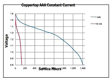
For the Coppertop AAA battery with a constant drain of 1mA, the battery will go down to 1.35V in about 500 hours. For a drain of 0.1mA (100 uA) I would expect it to be about 5,000 hours.
For a drain of 0.05mA (50uA) I would expect it to be about 10,000 hours, which is 416 days.
If you use the RTH2300 backlight sparingly the batteries might last a year. (Get the one without a backlight and use your own flashlight.)
AA
Let’s look at the AA battery.
The Ampere Hour capacity of an alkaline AA battery is about 2,100mAhr.
That doesn't mean you can get 2,100mA (2.1 Amps) from it for an hour.
The Ampere Hour capacity of a battery is generally measured with a lower discharge rate, such as 10% (which would be 210 mA).
Then there is the amount of time that the manufacturer says the battery will still be fresh (shelf life).
How much capacity will the battery have at the end of its freshness date?
There does not seem to a standard definition so I will assume 90%.
Most of the Duracell batteries I get have a freshness date 5 years away.
There are 43,800 hours in 5 years (1*24*365*5).
If we take 210mAhr (10% of 2,100mAhr), how much current does that represent for 43,800 hours (5 years)?
The answer is 4.79 uA. If we drain the battery with 4.79 uA for 43,800 hours, it will be 210mAhr, which is 10% of the rated capacity of 2,100mAhrs and we will have 90% left.
Therefore the self-discharge rate is about 4.79uA.
After a month it will amount to only 3,449uAHr or 3.449mA-Hr. (4.79uA * 24 * 30 = 3,449uAhr.).
If we allow 45uA for the thermostat we get a drain of 50uA. With a drain of 50uA how long before the 1.5V battery is down to 1.35V?
This chart is from Duracell. (For the complete datasheet click here.)
Figure 102
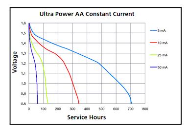
For the Ultra Power AA battery with a constant drain of 5mA, the battery will go down to 1.35V in about 250 hours. For a drain of 0.5mA (500uA) I would expect it to be about 2,500 hours.
For a drain of 0.05mA (50uA) I would expect it to be about 25,000 hours, which is 2.85 years.
It would be nice if the Honeywell RTH221B used AA batteries instead of AAAs.
Then you could use the version with the backlight (RTH2300) and maybe still have the batteries last a year.
CR2450 Lithium Coin Cell
The CR2450 Lithium coin cell has an amazing capacity of 650mAhr which compares favorably to the 1,000mAhr capacity of two AAA Alkalines.
The CR2450 is designed for a much lower discharge rate.
This chart is from the Panasonic Lithium Handbook by way of Mouser.
Figure 103
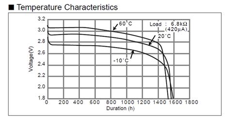
With a load of 420uA, at a temperature of 20 C, the time it would take for the voltage to drop 10% (from 3.0V to 2.7V) is about 1400 hours. With a load of 42uA I would expect it to take 14,000 hours which is 533 days (about a year and-a half.
At 6uA I would expect it to take 98,000 hours, which is 4,083 days, which is 11.19 years.
At 1uA I would expect it to take 588,800 hours which is 24,500 days, which is 67 years.
If we only want to let it drop to 2.8V (about 7%) we get about 1,100 hours (at 420uA). At 42uA it would be 458 days (1.2 years).
At 6uA it would be 77,000 hours, which is 3,208 days, which is 8.8 years.
At 1uA I would expect it to take 462,000 hours which is 19,250 days, which is 52.7 years.
A Lithium coin cell discharged at 1uA could last for 30 years. This chart is from Maxim Integrated Circuits. They make a great many integrated circuits, some of which incorporate lithium coin-cell batteries. https://www.maximintegrated.com/en/app-notes/index.mvp/id/505
Figure 104
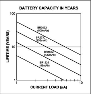
Lithium coin cells are an
impressive technology.
M. Gas or Electric?
You have probably heard that electric heat is much more expensive than gas heat to run.
That is probably true if the gas is natural gas.
But it might not be true if we are talking propane.
The reason is that while the price of natural gas is regulated, the price of propane is not.
Let’s run some numbers.
1. Altitude
From the furnace manual:
For elevation above 2,000 feet, derate furnace input 4% for each 1,000 feet of elevation above sea level. Derating is accomplished by reducing the orifice size.
See Derating Chart for orifice size.
As long as the proper orifice is used this is not a reduction in efficiency, just a reduction of the furnace rating.
My furnace is rated as 75K BTU/hr.
I live at an altitude of about 6,000 feet.
My furnace is derated by 6 * 4 = 24%.
Therefore, because I live at 6,000 feet my 75K BTU/hr furnace is really 75,000 * (1 - 0.24) = 57,000 BTU/hr.
That is what the furnace uses and what I pay for.
2. The BTU rating of a furnace is the input BTUs.
Then derate it for efficiency.
My furnace has a rated efficiency of 80%.
Therefore, the actual heat output of my furnace is 57,000 * 80% = 45,600 BTU/hr.
This is what the furnace will actually produce.
Most of the other 20% of the heat goes up the vent pipe. A small amount is radiated by the furnace cabinet which gets hot.
3. Home Propane is sold by the gallon and has about 91,500 BTU/Gallon.
Therefore, since the furnace uses 57,000 BTU/hr the propane usage is:
57,000 BTU/hr / 91,500 BTU/Gal = 0.623 Gal/hour
As an example, if propane costs $2.49/Gal it costs $2.49/Gal * 0.623 Gal/hr = $1.55/hr to run the furnace.
My propane company adds a HazMat fee and a Delivery Fee for each delivery regardless of the amount of propane they deliver. Since my main use of propane is for heating I factor these fees into the cost of propane.
BTW, propane weighs about 4.20 lbs/gal at 60 degrees (F) so a 20lb propane cylinder tank can hold 4.76 gallons. With this amount of propane 20% of the volume of the tank will be empty which is required to give the liquid propane space to become a gas. See: http://www.orangecoat.com/the-truth-about-filling-20-lb-bbq-grill-propane-tanks
4. Electricity
1 KWH = 3,412.142 BTU/hr
So 45,600 BTU/Hour is 13.36 KWH.
I will assume 95% efficiency for an electric furnace to account for some heat loss from the cabinet.
Therefore, an electric furnace would require 48,000 BTU/hour and use 14.07 KW.
For a cost of $0.11 per KWH this furnace would cost $1.55 per hour to operate.
By an amazing coincidence (which I made happen) this is the same cost as running an 80% propane furnace when propane is $2.49/gal.
Therefore, for a cost of electricity of $0.11/KWH an electric furnace will cost less to run when propane costs more than $2.49.Gal. That assumes an 80% efficient propane furnace.
You can get gas furnaces that are 95% efficient. That changes the equation.
5. For a 95% efficient propane furnace at 6,000 feet a 75K BTU/hr furnace will still be derated to 57,000 BTU/hr.
However, that 57,000 BTU/hr will produce 57,000 * 0.95 = 54,150 BTU/hr of actual heat.
Therefore, at 91,500 BTU/Gal at 54,150 BTU/hr that would still be 0.623 Gal/Hour of propane except it produces 54,150 BTU/hr instead of 45,600 BTU/hr. (Note that having a higher efficiency furnace does not mean you have to heat the house more. You could run the furnace less. This example is just to compare propane with electric.)
As an example, at $2.95/gal it would cost $1.84/hr.
For electric to produce 54,150 BTU/hr (at $0.11/KWH) it would require 16.71 KW.
1 KWH = 3,412.142 BTU/hr
54,150 BTU/Hour
95 % Efficiency (Assume some heat loss from the cabinet)
57,000 BTU/Hour Required
57,000 BTU/hr / 3,412.142 BTU/hr/KW = 16.71 KW (for an hour).
At $0.1100 per KWH this would cost $1.84 per Hour. (Again, an amazing coincidence that I made happen.)
Therefore, for a 95% efficient gas furnace and a cost of electricity of $0.11/KWH an electric furnace will cost less to run when propane costs more than $2.96/Gal.
That is quite a difference, isn’t it?
However, I have a problem with the 95% efficient gas furnaces.
What makes them 95% efficient is that they use a secondary heat exchanger to recover most of the heat that would otherwise go up the vent pipe. Indeed, they do such a good job recovering the heat that the vent pipe is PVC instead of steel.
By recovering so much heat it causes condensation of the exhaust gases.
Since the exhaust gas contains water vapor, NOx, some Sulfur (and other stuff) the condensation will contain water, nitric acid, sulfuric acid and some other stuff.
Even if the acids are weak acids and the secondary heat exchanger is made of stainless steel it will eventually corrode.
And the condensate line will dump this stuff onto or into the ground so don’t put any beloved plants near it.
Summary of Gas or Electric
|
Propane |
91,500 |
BTU/hr |
|
|
|
|
|
Furnace Rating (BTU/Hr) |
Altitude (feet) |
After Altitude Derating (%) |
Furnace Input (BTU/Hr) |
Efficiency (%) |
Actual Heating (BTU/Hr) |
Propane Gallons/Hr |
|
75,000 |
6,000 |
0.760 |
57,000 |
80 |
45,600 |
0.623 |
|
75,000 |
6,000 |
0.760 |
57,000 |
95 |
54,150 |
0.623 |
|
|
|
|
|
|
|
|
|
Electricity |
1 KWH |
BTU/hr |
(Not affected by altitude) |
|
|
|
|
|
|
|
|
|
|
|
|
Heating Required (BTU/Hr) |
Efficiency (%) |
Furnace Rating (BTU/Hr) |
Furnace Rating (KW) |
|
|
|
|
45,600 |
95 |
48,000 |
14.067 |
|
|
|
|
54,150 |
95 |
57,000 |
16.705 |
|
|
|
|
|
|
|
|
|
|
|
|
Costs |
|
|
|
|
|
|
|
Electricity (KWH) |
Furnace Rating (KW) |
BTUs Produced |
Cost/Hr |
|
|
|
|
$0.11 |
14.067 |
45,600 |
$1.55 |
|
|
|
|
$0.11 |
16.705 |
54,150 |
$1.84 |
|
|
|
|
|
|
|
|
|
|
|
|
Equivalent Propane |
|
|
|
|
|
|
|
Gas Furnace Efficiency |
Propane BTUs Produced |
Propane Gallons/Hr |
For Cost/Hr |
Propane Cost per Gal |
|
|
|
80% |
45,600 |
0.623 |
$1.55 |
$2.49 |
|
|
|
95% |
54,150 |
0.623 |
$1.84 |
$2.95 |
|
|
6. You can get a better deal with electric heat if you use a heat pump. However, heat pumps do not work well when the outside temperature is below maybe 45 degrees. That assumes you are using outside air as the heat sink. If you bury pipes in the ground and use water in the pipes you can use that as a heat sink. The frost line is defined as the depth at which water in the ground does not freeze. Therefore, water pipes are placed at or below the frost line so they won’t freeze.
If you go deeper you will reach a point at which the temperature of the ground is the yearly average temperature. That is where you want to put the pipes for a heat pump. See http://www.builditsolar.com/Projects/Cooling/EarthTemperatures.htm
Note that since heat pumps lose efficiency at low temperatures they also come with a heating element.
I would have some problems with a heat pump.
a. It can get very cold up here in the winter.
b. The ground at my house is basically rock with only a foot or two of dirt. Putting pipes in the ground would require a lot of work with a rock drill. Or maybe explosives. (Forget about using a backhoe.)
c. The compressor would be on (and making noise) whenever I was using heat. It would also shorten the lifetime of the compressor because it would be used more.
7. Until recently if you were using electric heat you could install some solar photovoltaic panels with a grid tie inverter to send the power back to the power company. In Nevada the power company (NV Energy) gave you a 100% credit for the power you send them. They didn’t pay you, it was a credit against the power you bought from them. (They did that because sending them power made the meter run backwards.)
Your solar panels would send them power during the day and you would use their power when you needed it, especially at night. It would also help reduce the cost of electricity during the Summer to run your air conditioning.
You could do all of this without batteries, although it did not give you any power when their power went out.
All that has changed. Now if you have solar energy (and connect to the Grid) NV Energy will charge you a higher rate that will result in you paying more for electricity than if you don’t have any solar. See http://lasvegassun.com/news/2016/jan/12/nv-energy-puc-price-solar-energy-beyond-residents/
I will note that this was done by the same Governor and Legislature that (as this is being written in March 2016) passed the largest tax increase in the history of Nevada. See http://news.yahoo.com/nevada-gop-governor-secures-unlikely-win-tax-increase-225132143--politics.html
One of the major solar energy installers (Solar City) is leaving Nevada. See http://www.reviewjournal.com/business/energy/solarcity-stopping-nevada-sales-installations-after-puc-ruling
Because of this some people will decide not to install solar.
Others will decide to install more solar + batteries and go completely off-grid. Or, if they are building a house, never go on-grid. There are a number of homeowners in my community who never went on the grid because NV Energy wanted so much money to run power lines to their house.
Solar panels will continue to get more efficient and cheaper. Batteries still need work.
There is considerable incentive for scientists and engineers to develop better batteries. Not just for home solar systems but also for electric cars.
NV Energy is being shortsighted. Eventually they will see their customer base shrink and then it will be too late for them to recover.
8. My propane furnace needs electricity to run the blower, about 800 Watts. No electricity = no blower = no heat.
How about this?
a. Use a reformer to crack propane (or natural gas) to make hydrogen.
b. Use the hydrogen in a fuel cell to make electricity to run the blower and the furnace controls.
c. Reformers and fuel cells are not very efficient and produce a large amount of heat, so add that heat to the furnace heat.
That way almost all of the propane (or natural gas) goes to producing heat (which is what a furnace is for) and your furnace will work whether you have electricity or not.
BTW, you might not have thought of this. All of the electricity used to run your furnace blower ends up as heat that is added to the air stream. It has no way to go anywhere else, not even the vent pipe. The 800 Watts of electricity that my furnace blower uses is about 2,700 BTUs.
N Conclusion
1. The propane furnace in my attic stopped working when the attic was cold.
2. The cause was probably marginal solder joints on the Control Board that were stressed by thermal cycling over the years.
3. The problem only manifested after the Guy from Company A left the cover plate off the box (in the Blower Compartment) where the Control Board is located. Normally the heat produced by the Control Board gets trapped in the box and keeps the Control Board warm. The Control Board is also warmed by the Return air when the furnace is running, but first the furnace has to run long enough for there to be Return air.
4. In order for the Flame Sensor circuit to work, the 120VAC Mains must have Neutral and Ground connected together. According to the National Electrical Code this may only be done (and is required to be done) at the service entrance to the building and no place else. As a result, an electrical connection problem outside the furnace at the service entrance may cause the flame sensing circuit to malfunction even though there is no problem in the furnace itself.
5. The way the power supply in the Ruud Control Board is done creates a difference in the voltage references between the Flame Sensor circuit and the circuit used to detect the presence of a flame. This reduces the effectiveness of the Flame Sensor.
6. The phase of the 24VAC furnace transformer makes no difference in the operation of the Flame Sensor.
7. The old Rudd Control Board that I have (# 62-24084-01 from 1995) does not flash an Error Code when there is an error, which makes diagnosing problems more difficult than it already is.
8. The Ruud Control Boards (both the 62-24084-01 and the current model 62-24084-82) are single-sided printed circuit boards which I consider a poor choice for a piece of critical equipment (a furnace) that may be subject to substantial thermal cycling.
9. A company called ICM Controls makes a replacement Control Board (ICM288) that is on a double-sided printed circuit board that I consider superior to Ruud’s Control Board. The ICM288 also costs less.
10. Many of today’s thermostats cannot be powered by the 24VAC furnace power. This is so they can work with 90-year old furnace installations that provide only two wires to the thermostat. Some of these thermostats use Power Stealing. Some use only their batteries. Some of the thermostats that use only their own batteries need to have their batteries replaced every year. Others can run for many years without needing new batteries.
11. Before you buy a WiFi thermostat find out what security protocols it uses and whether the manufacturer’s Web site that you would use to access your thermostat from the Internet really uses https: .
12. I want a smart furnace that does extensive diagnostics, logs them with a timestamp, and lets me access the data with WiFi. I want the furnace to use WiFi Direct so I can talk to the furnace directly with a Tablet or through my home wireless network. I want just a basic thermostat in case the furnace WiFi stops working.
And that is what I have learned about furnaces and thermostats.
Jed Margolin
Virginia City Highlands, Nevada
March 22, 2016
Copyright 2016
Jed Margolin
Epilogue
Did you know that many thermostats operate solely on their batteries? Does yours?
Did my article save you from waking up one morning to a freezing-cold home?
Perhaps I even saved you from a service call where the service tech told you:
1. Everything is fine, your thermostat just needed new batteries.
2. That will be $200, please.
Perhaps you have a Rheem/Ruud furnace and you needed the schematic for the furnace control board.
Perhaps I helped you fix it so you didn’t need a service call. Or a new furnace.
If you value what I have taught you and given you, you can show your appreciation by sending me $2.75 by PayPal. (If you want to send me more, that would be ok too.)
To do this log into your PayPal account (www.paypal.com), find the Send button, and click on it. Then enter my email address (jm@jmargolin.com) and then the amount.
Thank you.
And stay warm.
Jed
.end