BME280 Tester Jed Margolin 1/29/2021
This project is for testing the Bosch BME280 sensor.

The BME280 sensor measures temperature, absolute air pressure and humidity. I use it in my project My TX4 Wireless Sensor Transmitter to replace the La Crosse TX4U wireless sensor which is no longer made. Click Here. (I live in the mountains 22 SE of Reno, Nevada, at an altitude of about 6,000 ft. That is why the absolute air pressure is about 825 mb. When the air pressure at sea level is 1013 mb it is 812 mb up here.)
The board can also be used for developing the software for other sensors that use either the SPI or I2C interface. An example is the HTU21D made by TE.
In addition I use it to receive SPI messages from another project and display the data on the LCD.
When I started using the BME280 I discovered a problem. Several times when I have bought the BME280 on eBay the sellers have sent me the BMP280. The BMP280 measures temperature and absolute air pressure (no humidity). I also received some BME280 sensors that gave erroneous readings of the temperature and humidity. :-(
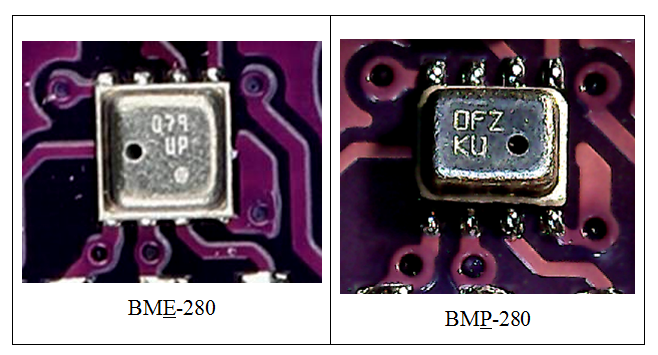
One way you can tell the difference is that the BME280 is square with the hole on the left while the BMP280 is rectangular and has the hole on the right. They also have different device IDs which are programmed into the part and which you can read.
For a more complete explanation Click Here.
The definitive test is to read the part and display the values and the device ID. That is what the BME280 Tester is for.
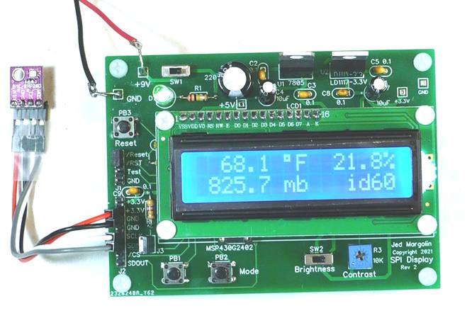
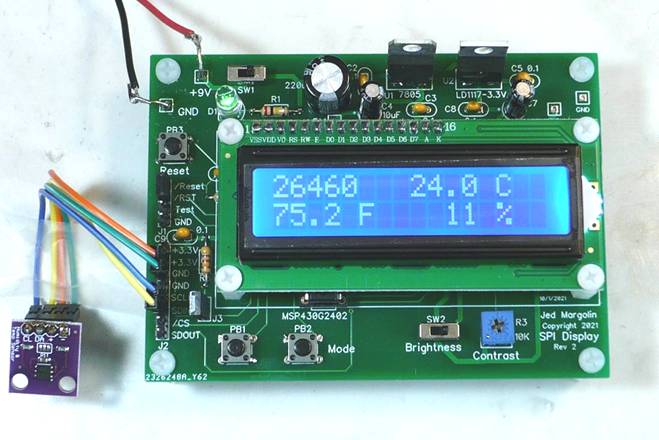
In this picture I am using a BME280. The ID code is 60.
In this picture I am using a BMP280. The ID code is 58.
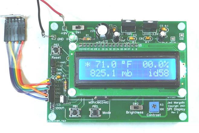
The BMP280 does not have a humidity sensor so it reads 00.0%.
Note: The asterisk blinks on and off to show that the program is running.
The data sheets for the BMP280 and the BME280 show how to process the data. It isn’t easy.
For the data sheet for the BMP280 Click Here.
For the data sheet for the BME280 Click Here
The skill level for stuffing the board is: Intermediate. Make sure you use a temperature-controlled soldering iron. I use a temperature of 340 degrees Celsius.
To compile the source code and download it into the microcontrollers I use Texas Instruments Code Composer Studio. It is free and is on this page: https://www.ti.com/tool/MSP-EXP430G2ET where you can get the versions for Windows, Linux and macOS.
The direct link to the current version for Windows is: https://software-dl.ti.com/ccs/esd/CCSv10/CCS_10_4_0/exports/CCS10.4.0.00006_win64.zip .
The skill level to use Code Composer Studio is: Advanced. (Maybe Really Advanced).
Files
I am providing the following files:
1. Schematic: jm_bme280-tester_schematic.pdf
2. Bill of Material: jm_bme280-tester_bom.pdf
3. Source Code: jm_bme280-tester_source.zip
Contains:
main.c
main.h
lcd.c
lcd.h
bme280.h
bme280.h
The source code is complete. It does not require any libraries other than the ones that come in Code Composer Studio.
4. Gerber files: jm_displ-r2.zip
You can order blank PC Boards from PCBWAY (they will give me a small royalty):
https://www.pcbway.com/project/shareproject/BME280_Tester.html
Notes:
1. After you stuff the board clean off the flux. I am Old School so I use acetone but the official recommendation is to use common rubbing alcohol. You can get 90% rubbing alcohol so it contains only 10% water.
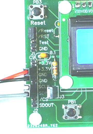
2. Many I2C parts need to have SDA pulled up through a 4.7K resistor. That is what J3 and R5 are for.
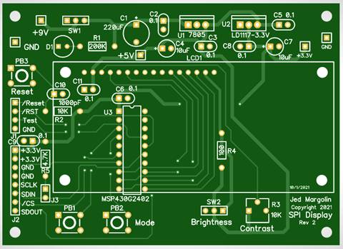
3. This is the bare board top:
This is the bare board bottom:
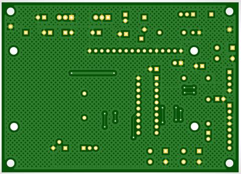
The good ground plane coverage didn’t happen by accident. It certainly didn’t happen by using the auto-router. I routed all of the traces by hand to get good ground plane coverage.
4. I put the MSP430G2402 in a socket. Always use sockets with machine-tooled pins. The sockets with leaf-springs are crap.
5. When you get the Launchpad, if you want to use it by itself to become familiar with it and Code Composer Studio and you want to use the crystal, you have to jumper the two sets of pads labeled R5 and R7. Here is the MSP-EXP430G2ET User Guide: http://www.ti.com/lit/pdf/slau772.
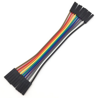
6. To program the MSG430G2402 you connect the SPI Display board to the Launchpad with three of these wires: Breadboard Jumper Wires 10cm Dupont Wire, Female to Female.
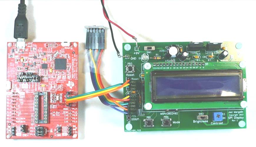
When you use it this way you cannot have an MSP430G2xxx in the Launchpad’s socket, the part is on the SPI Display Board.
To make it run standalone remove the three wires and use a header plug to connect the /RES and /Reset pins on the header (on the SPI Display Board).
I mentioned that the SPI Display Board can be used to develop the software for other sensors. The HTU21D is an example. I have done that.
Source Code: jm_htu21d-tester_source.zip
Contains:
main.c
main.h
lcd.c
lcd.h
htu21d.c
htu21d.h
For the data sheet for the HTU21D Click Here.
This is the display for the HTU21D. It shows the raw temperature, the compensated temperature in Celsius, the compensated temperature in Fahrenheit, and the compensated humidity,
You can use the SPI Display for other sensors. All you have to do is program it yourself. :-)
Addendum
I also use the board to receive data using the SPI interface and display it on the LCD. That is why I originally made the board.
The board I use it with demonstrates my U.S. Patent 9,784,449 Flame Sensing System issued 10/10/2017 to Margolin (that’s me).
ABSTRACT OF THE DISCLOSURE
This invention relates to the field of sensing flames in equipment such as gas furnaces by using the electrical properties of flames. In a first group of embodiments flame rectification is used to cause distortion of a signal having a selected waveform. A harmonic of the distorted waveform is detected thereby providing flame proof. In a second group of embodiments flame rectification is used as a mixer to cause two signals having selected waveforms to produce sum and difference signals. The sum and/or difference signals are detected thereby providing flame proof.
The method commonly used in residential gas furnaces is to use flame rectification to produce a DC voltage.
Although flames conduct current better in one direction than the other the difference isn’t very much, so calling it Flame Rectification gives it too much credit. But it is enough to cause harmonic distortion of a single signal or cause two signals to heterodyne. Only a flame does that. Dirt and grime on the wires and the board is only resistive. And my system works at the lower voltages used in furnace control boards.
The method used in my demonstration board is to use flame rectification to cause two signals (874 Hz and 1,262 Hz) to heterodyne. The difference frequency (388 Hz) is detected using quadrature synchronous detection. Although my patent shows the methods using MSI integrated circuits my demonstration board uses a Texas Instruments MSP430G2252 microcontroller to generate the two signals for the flame rod and the difference signal for the analog switches that perform the quadrature detection of the 388 Hz difference signal. It does this by using the 388 Hz signal to make an opamp either inverting or non-inverting. This does 4-quadrant multiplication (an analog input times a bipolar digital input). These opamps are followed by DC filters, one for the in-phase signal and another for the quadrature signal. The outputs of the DC filters are read by the MSP430G2252 which does the level shifting, full wave rectification, magnitude calculation, and the threshold test for the flame detection.
I made a second demo board where the quadrature detection and DC filtering is also done by the MSP430G2252. The advantage of the first demo board (with analog switches used as analog multipliers) is that you can see the operation of the quadrature detection with an oscilloscope so you don’t have to wonder if the software is doing it right.
The following picture is of the first demo board with the SPI Display board.
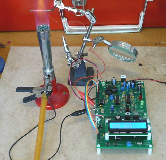
(In this picture I am using the previous rev of the SPI Display Board. To make the current rev I replaced the LM317 voltage regulator, two resistors, and a trimpot with the LD1117-3.3V regulator and added the 4.7K pullup resistor for the SDA line.)
I did the development using a Meker burner which is like a Bunsen burner but has a wider flame. I did the final verification using an actual furnace. (My flame sensing system works even better in a real furnace.)
You can read the patent at www.jmargolin.com/flame/flamepat.htm
You can also read why I invented this new flame sensing system (I had a problem with the furnace in my attic): www.jmargolin.com/furnace/index.htm
This patent is available for sale or license.
Jed Margolin
Virginia City Highlands
Nevada
11/29/2021 Updated 1/2/2022
.end