My TX4 Wireless Sensor Transmitter Jed Margolin 11/15/2021
My TX4 Wireless Sensor Transmitter replaces the La Crosse TX4U wireless sensor which is no longer made.
I bought a La Crosse WS-9025U Weather Projection Station from Costco in October 2003 for $43.29 . It projects the time and outdoor temperature on the ceiling, which I like. It also receives WWVB to set the time. My WS-9025U spent its first two years in the mild climate of San Jose (California) and then 13 years in the Virginia City Highlands in Nevada where the temperatures can go from 0 degrees (F) in the Winter to 100 degrees (F) in the Summer.
Three years ago the outdoor sensor started eating batteries faster than it used to. Then I started getting an error message of OF.L for the outdoor temperature. That meant that the temperature/humidity sensor was bad. The transmitter part was still working but the data was bad.
La Crosse does not make the TX4U sensor anymore. For awhile they said to use the TX7U. Now their Web site doesn’t mention it at all. Besides, the TX7U Sensor cost too much ($28.65 on Amazon) and has gotten some bad reviews.
La Crosse doesn’t make the WS-9025U anymore either. Companies (including La Crosse) make new units that do projection but they get generally bad reviews. And they are ugly.
The sensing element in the TX4U is unknown so replacing it was not an option. So I decided to see if I could make my own TX4U replacement.
Most of the work on decoding the data protocol was already done by others. Most people who were interested in reverse engineering the La Crosse TX4U Sensor were interested because they wanted to be able to receive its signal, decode it, and use the temperature and humidity in their own projects. I found this explanation of the data essential to making my own: http://www.f6fbb.org/domo/sensors/tx3_th.php. The Webmaster is Jean-Paul ROUBELAT - F6FBB. Check out his home page: http://www.f6fbb.org/
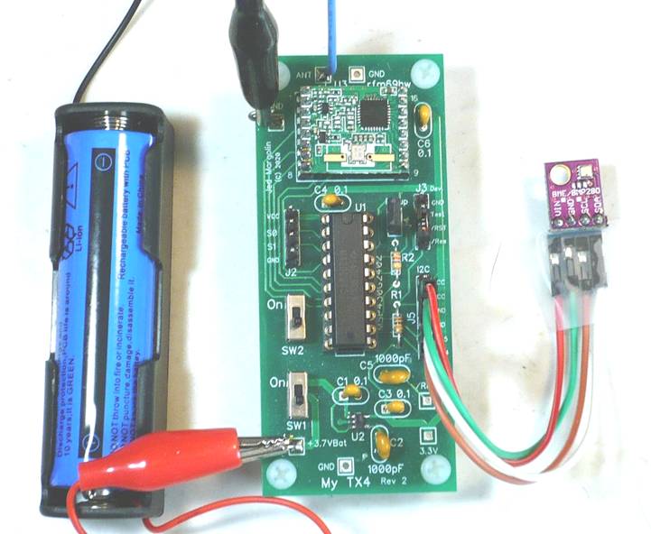
Since I wanted to make the wireless sensor I had a small amount of work to do. Although my La Crosse TX4U went bad it was still transmitting, only it was transmitting bad data from the bad sensor. The La Crosse used a separate transmitter module so it was easy to find the pin with the data on it. I used my $10 logic analyzer USB pod. On eBay search for: 24MHz 8 CH USB Analyzer 8 Channel Logic Analyzer. It works really well with this open source software: https://sigrok.org/wiki/Downloads.
To save the screen shots I use the Snipping Tool that comes with every version of Windows. It allows you to select a window for the screen capture. Find SnippingTool.exe on your PC, send it to your Desktop, then drag it to your toolbar. You can save the screen capture as a PNG file or you can just paste it.
The following is part of what I found the TX4U doing.
When the TX4U sends data it sends two identical packets of 44 bits. I will call it a data frame.
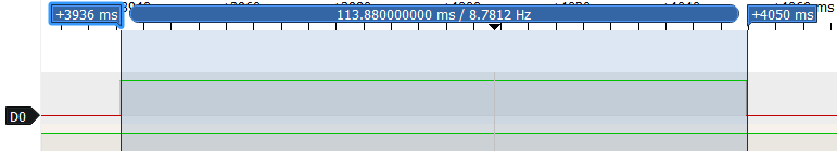
Power-Up starts with a pulse followed by two frames of data.

The Power-Up pulse lasts 114 ms.
The first frame starts 241 ms after the end of the Power-Up pulse.
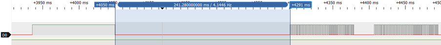
The time between data packets is 29 ms
The second frame starts 301 ms after the end of the first frame.

The next and succeeding frames do not have the power-up pulse, only the data frames.
There is much more but since I did it, you don’t have to.
The TX4U operates at 433 MHz (technically 433.92MHz) and uses OOK (On-Off Keying) which means that the transmitter is turned on-and-off to transmit data. That is opposed to protocols such as FSK (Frequency Shift Keying) where the carrier is always on during the transmission but the frequency is shifted to transmit data. OOK systems are less resistant to noise than FSK but the transmitters and receivers can be simpler and therefore cheaper. Because of the use of 433MHz for so many things you can buy cheap transmitters and receivers on eBay. Many are sold for use with the Arduino so you can have your own cheap (but slow) RF communications link.
The first transmitter I used was the STX882.
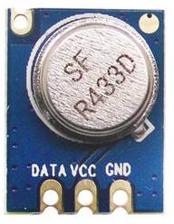
The STX882 is rated to work down to -20 degrees C (-4 degrees F). It didn’t. It stopped working below -3.8 degrees C (28 degrees F). I tried several. No joy. A similar transmitter module (maybe the same but older version) is the FS1000A.
Since that didn’t work I am using the RFM68HW made by HopeRF (https://www.hoperf.com/). They make several versions of the RFM69. I chose the RFM69HW (433 MHz version). The pins are on 2.00mm centers (not 2.54mm = 0.1”) so you need 2.00mm headers. The RFM69 is a transceiver for sending and receiving digital data packets but can be configured for OOK. For complete info for the RFM69HW go here: https://www.hoperf.com/%20modules/rf_transceiver/RFM69HW.html
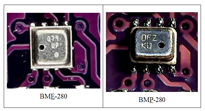
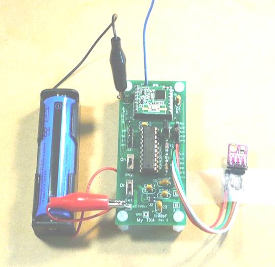
For the sensor I used the Bosch BME-280 which measures temperature, absolute air pressure, and humidity. (I have experience with the Bosch BMP-280 sensor which measures temperature and absolute air pressure.) I have had two problems with the BME-280.
1. Several times when I have bought the BME-280 on eBay the sellers have sent me the BMP-280. The way you tell the difference is that the BME-280 is square with the hole on the left while the BMP-280 is rectangular and has the hole on the right. They also have different device IDs which are programmed into the part and which you can read.
For a more complete explanation Click Here.
2. I have recently checked to see what they cost (for this article in November 2021) and they have doubled or tripled in cost on eBay. Now they cost too much.
If you don’t need the humidity you can use the BMP-280. Then if the price of the BME-280 comes back to Earth you can use that one.
The data sheets for the BMP-280 and the BME-280 show how to process the data. It isn’t easy.
For the data sheet for the BMP-280 Click Here.
For the data sheet for the BME-280 Click Here
The skill level for stuffing the board is: Intermediate. Make sure you use a temperature-controlled soldering iron. I use a temperature of 340 degrees Celsius.
To compile the source code and download it into the microcontrollers I use Texas Instruments Code Composer Studio. It is free and is on this page: https://www.ti.com/tool/MSP-EXP430G2ET where you can get the versions for Windows, Linux and macOS.
The direct link to the current version for Windows is: https://software-dl.ti.com/ccs/esd/CCSv10/CCS_10_4_0/exports/CCS10.4.0.00006_win64.zip .
The skill level to use Code Composer Studio is: Advanced. (Maybe Really Advanced).
Notes:
1. The antenna is a piece of #20 solid wire 6.50” long (¼ wavelength at 432.9 MHz.) Add 1/8” to solder it to the board.
2. My TX4 runs on a 18650 Lithium-Ion rechargeable battery. With the batteries I buy on eBay it lasts 6-8 months. To get longer battery life you could put two in parallel. Or you could use a small solar cell with a battery-charge IC.
3. La Crosse says to put the batteries in the transmitter first, then put the batteries in the display. In other words, first you turn on the transmitter, then (within 30 seconds) you turn on the receiver (the base unit). When you turn on the transmitter it selects a random ID code. This allows you to use multiple sensors and base units.
Turning the transmitter on first always seemed wrong to me. When I started this project I found that when you turn on the transmitter it waits 30 seconds before sending the first transmission. The first transmission is special so that the base unit will recognize it as an initialization transmission. And when you start the transmitter it randomly selects a 7-bit ID. That way La Crosse didn’t have to spend money on a DIP switch. If it selects an ID that you (or your neighbors) are already using then just try again.
This is what I do.
a. I start the receiver first, wait for it to boot-up, and then turn on the transmitter. When I start my transmitter it immediately starts the first transmission.
b. Instead of sending a random ID I send a fixed ID. I have a switch so I can select two different IDs. If they are somehow both being used by other devices, you have the source code so you can select different IDs, recompile the program, and reload it into your MyTX4.
4. You may have noticed that I use a TC-1014-3.3V regulator. This is a surface mount device (SMD). I couldn’t help it. It uses very low current for itself which is necessary to have a decent battery life.
If, like me, you don’t have the special equipment for doing SMD you can do it anyway.
This is how I do it.
1. I cut a thin strip of masking tape about an 0.75” long. I do it by putting tape on a piece of metal and using a second piece of metal (with a very straight edge) and cutting the strip with an Exacto knife.
2. I put the strip on the TC-1014 to pick it up and put it on the board.
3. Using two wooden toothpicks I push the masking tape around on the board until the TC-1014 is properly centered on the pads.
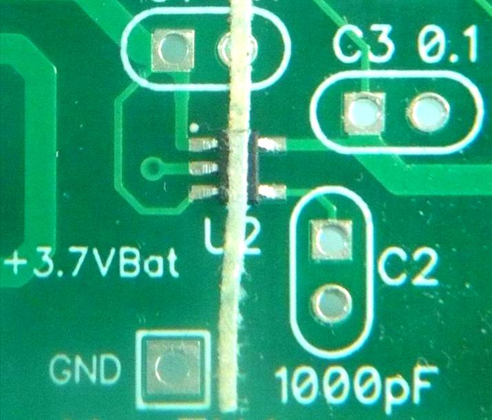
4. Then I solder the legs starting with one corner.
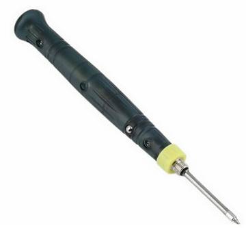
Soldering the part requires a soldering iron with a very small tip and using some 0.015” (0.3mm or 0.4mm) diameter solder. I use a USB soldering iron (5V 8W). It has a very small tip.
A computer USB port might not be able to supply enough current. And you should not use a cheap USB power supply. These power supplies use a switching regulator directly off the Mains and can have a leakage voltage of up to 40VAC. The current is very low (tens of microamps) but it is enough to blow the gate of an IGFET (Insulated Gate FET). It could also blow the inputs of an opamp with high impedance inputs. The solution is to use a USB battery pack with nothing else connected to it. And remember to discharge yourself to ground because you might have picked up a charge walking over carpet.
5. Remove the masking tape.
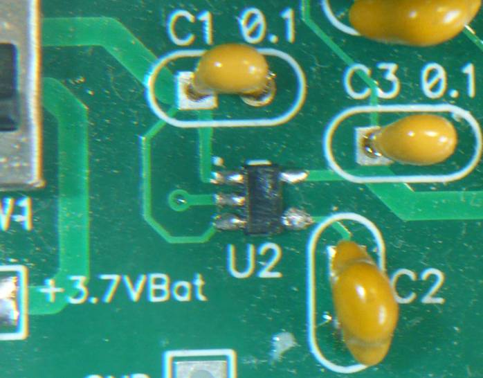
6. Then I load C1, C2, and SW1.
7. Then I test it with the 18650 battery. If it doesn’t give you 3.3V you might have put solder on a pad without soldering it to the tiny leg.
8. Once it works I clean off the flux and the adhesive left from the masking tape. I am Old School so I use acetone but the official recommendation is to use common rubbing alcohol. You can get 90% rubbing alcohol so it contains only 10% water.
9. Let it dry. Then I use clear acrylic (clear nail polish) on the part to protect it.
Files
I am providing the following files:
1. Schematic: jm_mytx4_schematic.pdf
2. Bill of Material: jm_mytx4_bom.pdf
3. Source Code: jm_mytx4_source.zip
Contains:
main.c
main.h
bme280.h
bme280.h
rfm69.c
rfm69.h
The source code is complete. It does not require any libraries other than the ones that come in Code Composer Studio.
4. Gerber files: jm_mtx4-rfm69hw-r2.zip
You can order blank PC Boards from PCBWAY (they will give me a small royalty):
5. Suppose you get it all together, start it up, and you don’t get anything on the base unit? Is it the BME-280/BMP-280 sensor, the rfm69hw, or the base unit?
I have written a test program that doesn’t use the sensor. Using the rfm69hw it transmits a temperature of 24.3 degrees C (75.7 degrees F) and a humidity of 23%. If the base unit receives it correctly then the problem is with the sensor. (BME-280/BMP-280).
Source Code: jm_mytx4_rfm69hw-test.zip
Contains:
main.c
main.h
rfm69.c
rfm69.h
The source code is complete. It does not require any libraries other than the ones that come in Code Composer Studio.
If the base unit does not receive it correctly (or at all) then the problem is either with the rfm69hw or the base unit. You can get a good idea if the problem is with the rfm69hw by using a USB SDR (Software Defined Radio) dongle. You can get them (with an antenna) on eBay for less than $20. Do a search for “SDR Receiver With Antenna RTL2832U”. They typically look like this:
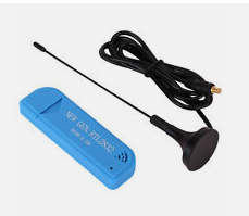
The software to use is SDRSharp. It is free. (https://airspy.com/download/) You might find it interesting to see what else is up there around 433 MHz.
The SDR uses an IC that was developed for a TV tuner. The pod receives 25MHz to 1760MHz. That includes the FM broadcast band (88MHz - 108MHz) and the frequencies used by aircraft for ADS-B (978 MHz or 1090 MHz). ADS-B periodically transmits the aircraft’s identification, current position, altitude and velocity, Most aircraft are now required by the FAA to have ADS-B. (https://www.faa.gov/nextgen/programs/adsb/faq/) There is free software to use with the SDR to receive ADS-B (https://www.rtl-sdr.com/adsb-aircraft-radar-with-rtl-sdr/)
More Notes
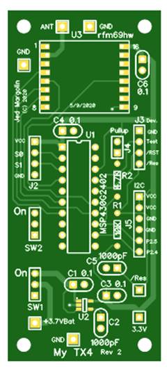
1. This is the bare board top:
This is the bare board bottom:
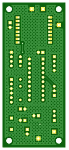
The good ground plane coverage didn’t happen by accident. It certainly didn’t happen by using the auto-router. I routed all of the traces by hand to get good ground plane coverage.
5. I put the MSP430G2402 in a socket. Always use sockets with machine-tooled pins. The sockets with leaf-springs are crap.
6. When you get the Launchpad, if you want to use it by itself to become familiar with it and Code Composer Studio and you want to use the crystal, you have to jumper the two sets of pads labeled R5 and R7. Here is the MSP-EXP430G2ET User Guide: http://www.ti.com/lit/pdf/slau772.
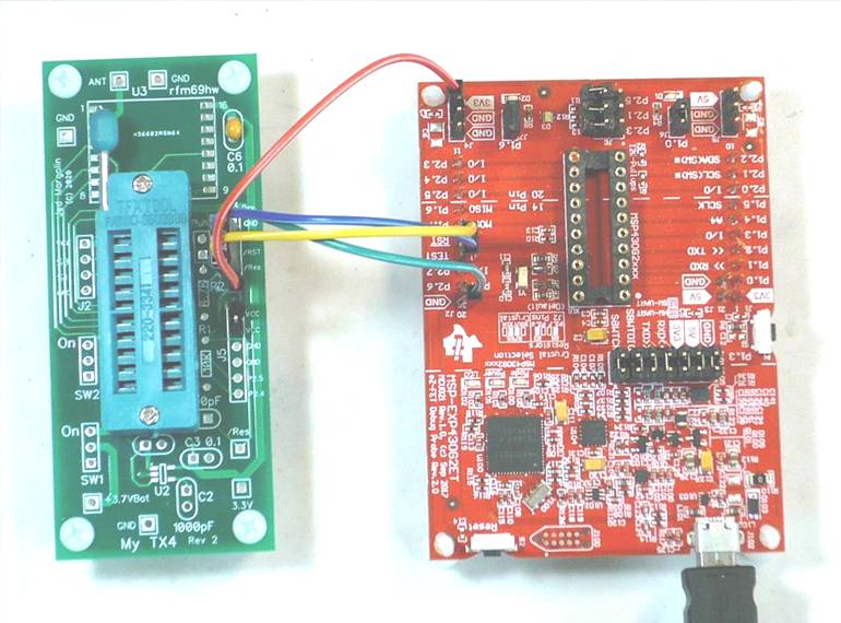
7. To program the MSG430G2402 you connect the MyTX4 board to the Launchpad with three of these wires: Breadboard Jumper Wires 10cm Dupont Wire, Female to Female.
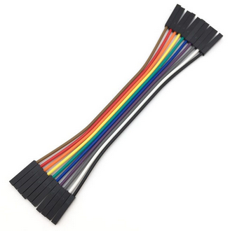
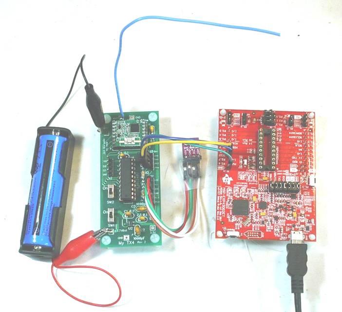
When you use it this way you cannot have an MSP430G2xxx in the Launchpad’s socket, the part is on the MyTX4 Board.
To make it run standalone remove the three wires and use a header plug to connect the /RES and /Reset pins on the header (on the MyTX4 Board).
The board can be used for other things
A. Programmer with Zero Insertion Force (ZIF) socket.
I have some other projects that do not have the Launchpad port on them. When you plug a part into the Launchpad to program it you risk bending a pin. When you straighten the pin it almost always breaks off.
You can stuff a Textool ZIF in the MyTX4 board. It is a tight fit but it does fit.
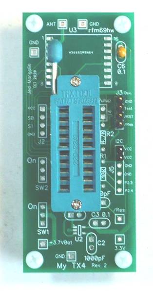
Stuff C6 bypass capacitor, three of the pins of J3, and two pins of J5. (If you stuff two pins on J5 you can solder it without burning your finger.)
Connect as follows.
|
Launchpad |
MyTX4 |
|
GND |
J3 - GND |
|
TEST |
J3 - Test |
|
/RST |
J3 - /RST |
|
3V3 |
J5 - VCC |
B. Breakout Board For The RFM68HW
Stuff the RFM68HW on the board. Stuff the C6 bypass capacitor. Stuff two 1x10 headers instead of the socket for the MSP430G2402.
This gives you access to the following RFM68HW pins: GND, VCC, RESET, the SPI port and DIO2. If you need more of the signals you can connect them with jumper wires (like #30 Wire Wrap wire) to the header in the MSP430G2402 pads.
Some Ideas
A. Instead of using the BME-280/BMP-280 you can use any sensor that uses either an SPI or I2C interface. (All you have to do is program it,.)
B. You may have noticed header J2. It brings out GND, VCC, P1.0, and P1.1. You can use it to read and transmit your own digital signal instead of the BME-280/BMP-280. If you use an MSP430G2553 (or other MSG430G2xxx with the ADC) you can send an analog signal to the base unit. You could, for example, make a moisture sensor. You could connect it to a pot that is moved by something. If you use this input make sure it stays within 0V to 3.3V.
C. The RFM69HW is a transceiver for sending and receiving digital data packets and the packets are addressable. It seems a shame to use it for On-Off-Keying.
You can make your own wireless weather sensing system. Use the MyTX4 board to send data packets to an RFM69HW connected to a Raspberry Pi.. That enables a myriad of possibilities.
1. You can have up to 128 sensors.
2. Sending the sensor data every minute seems excessive. Do you really need to know the outdoor temperature by the minute? If you send it every 5 or 10 minutes you will prolong the battery life.
3. You could use one or more in your house. If you live in an area where it gets below freezing sometimes, and you have water treatment equipment in your garage, you do not want it to freeze. If the temperature starts to approach freezing you need to do something about it like turn on a portable electric heater aimed at the water treatment equipment.
Usually there is enough warmer air in the garage so it won’t go below freezing. But what if someone has left the garage door open?
4. You can keep a log of the temperature and humidity.
Some caveats:
1. The RFM69HW is so programmable that people have trouble programming it to work reliably so be prepared to spend some time on it. And always do handshaking with your base unit. Your base unit should keep track of when the last reliable communications was.
2. If you are going to do this I recommend you use the 915MHz version. There will be less interference than with all the stuff at 433MHz.
D. This is purely speculative. This is about figuring out a good place to drill a well.
I live in the Virginia City Highlands, Nevada. We are located in the mountains 22 miles SE of Reno. We all have wells or, in the extreme, some people have water delivered.
Drilling a well is always an iffy proposition. If you end up with a dry hole you still have to pay the drilling company.
You can drill two holes 20 feet apart. One can have water and the other one can be dry.
This is why.
Our water comes through fractured rock in the ground from Lake Tahoe, about 22 miles away.
Lake Tahoe is at an altitude of 6,225 ft. My community has an average altitude of around 6,000 feet. (Reno averages 4,500 feet.)
Yet somehow there is enough hydrostatic pressure to bring us water (after you drill down far enough). Since it is coming through fractured rock whether you get water depends on how the rock is fractured.
So here is the Plan.
The Moon raises tides in the ground as well as the water, only the ground tide is much smaller.
My mountain is mostly iron. Iron is ferromagnetic which is why it is used in transformers, motors, and generators.
The Earth has a magnetic field.
As the Moon raises tides in the mountain it will change the magnetic field slightly.
So, put down 100 sensors in a 10 x 10 array, each 1 meter apart,
Each sensor will have a very sensitive magnetic sensor with very low drift. They will use the MyTX4 board to send the data to a Raspberry Pi, say every 6 minutes or so.
After some period of time the data will be analyzed using the algorithms used for tomography. These are the algorithms used in CAT scans (Computer Aided Tomography) and in MRIs to produce 3D images. The period could be as short as one day (two lunar tides) or preferably a month. If it changes during the month it means the Sun is also involved.
So:
1. Will the data allow you to produce a 3D picture of the ground underneath?
2. If so, how far down will it show?
and
3. Will it be useful in determining where to drill a well?
More than 43 million people—about 15 percent of the U.S. population—rely on domestic (private) wells as their source of drinking water.
If you are a grad student at a university this might be a good Master’s thesis. Maybe even a Ph.D thesis.
If it works out you could start a company. If you do, it would be nice if you gave me a piece of the company.
Regarding patents. It would be nice if you list me as a co-inventor.
You have one year to file a Provisional Application in the U.S. The U.S. has a First-to-File system.
Then you have one year to file a Non-Provisional Application.
The clock starts now.
Jed Margolin
Virginia City Highlands
Nevada
11/15/2021 Updated 1/2/2022
.end