GPS Clock and Armageddon Alarm Jed Margolin 10/9/2021
A GPS Module using the U-blox NEO6MV2 is used to receive the GPS timing signals to show the exact time on a 16x2 LCD display.
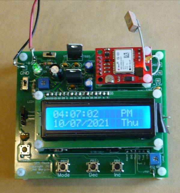
In addition to the display, the end of each minute is signaled with a musical cord. To hear it Click Here.
The board uses a Texas Instruments MSP430G2553 to receive the GPS messages from the GPS Module and an MSP430G2402 that uses PWM to produce a nice sine wave tone for the musical notes. (If you don’t want the musical tones you can leave that part of the board unstuffed.)
Each microcontroller has a three-wire port that connects to an inexpensive Texas Instruments Launchpad (MSP-EXP430G2ET) to program the microcontroller. After the microcontroller is programmed you remove the three wires and use a header plug between /RES and /Reset to make it run standalone.
My GPS Clock has several selectable modes.
1. Display the Local Time/Date.
2. Display the UTC Time/Date.
3. Select Local Time in 12 hour or 24 hour format.
4. Select UTC offset for Local Time.
5. Select whether DST is observed.
6. Display DST Start and End dates for the current year.
7. Display Number of GPS Satellite in view.
8. Armageddon Alarm Mode.
The offset for the local time, and whether DST is observed, is stored in the MSP430G2553’s User Flash Segment C. If it has not been set the default is Pacific Time with DST observed.
The Armageddon Alarm Mode requires some explanation.
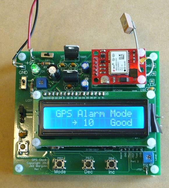
The unit starts by waiting to acquire at least five GPS satellites. If the GPS module has not been powered up recently it may take several minutes to acquire the satellites. It may take several more minutes for the PPS (Pulse Per Second) LED to start flashing. Indeed, it has sometimes taken 20 minutes to get started. Typically, I get 11 or 12 satellites where I live. If the number of GPS satellites drops to three or fewer then something bad is happening.
The odds that the GPS system is having a technical problem are vanishingly small.
What is happening is Armageddon.
Armageddon can happen in several ways.
One way is for the Sun to emit a huge coronal mass ejection (CME) that hits the Earth. The CME will induce damaging currents in anything that conducts electricity. This will burn out the power grids (the Eastern Grid, the Western Grid, and the Texas Grid) and most electrical devices except for those that have been specially “hardened” against it (in a Faraday cage).
A huge CME will burn out most (probably all) of the satellites in Earth orbit including the GPS satellites starting on the sunward side of the Earth and then quickly spread to the nightside by the Earth’s magnetic field. See https://en.wikipedia.org/wiki/Coronal_mass_ejection. There was a huge CME in 1859 (the Carrington Event) that burned out telegraph lines all over North America. See https://en.wikipedia.org/wiki/Carrington_Event. The reason it didn’t burn out anything else is because there wasn’t anything else. No power lines, no telephone lines, no radio, no television, no cell phones, no Internet. There were just telegraph lines and a telegraph system that operated from batteries. (When your telegraph battery ran down you swapped it for a spare and sent the old one back to the factory to be rebuilt.)
The other way for Armageddon to happen is a Global Thermonuclear War.
The first thing everyone will do when they start Armageddon is destroy or otherwise disable everyone else’s satellite navigation systems.
The GPS Clock With Armageddon Alarm will give you instant notice by playing this: Click Here. It also provides a 3.3V logic level signal that you can connect your own alarm to. (The interface depends on what your alarm is so you will have to do that yourself.)
The skill level for stuffing the board is: Intermediate. Make sure you use a temperature-controlled soldering iron. I use a temperature of 340 degrees Celsius.
The skill level for installing and using the two pieces of software is: Advanced.
1. To compile the source code and download it into the microcontrollers I use Texas Instruments Code Composer Studio. It is free and is on this page:
https://www.ti.com/tool/MSP-EXP430G2ET where you can get the versions for Windows, Linux and macOS.
The direct link to the current version for Windows is: https://software-dl.ti.com/ccs/esd/CCSv10/CCS_10_4_0/exports/CCS10.4.0.00006_win64.zip .
The skill level to use Code Composer Studio is: Advanced. (Maybe Really Advanced).
2. The U-blox NEO6MV2 allows you to enable the GPS messages that you want and disable the messages that you don’t want. I use "GNZDA" (or “GPZDA”) for the time and "GPGSV" for the number of satellites in view. I disable all of the other messages.
To do that you need the U-blox U-Center 2 software available for free at https://www.u-blox.com/en/product/u-center . (It is only for Windows.)
You also need to connect the module to a PC.
First, there is something you need to know about serial ports.
1. There is the logic protocol (the Ones and Zeroes). The NEO6MV2 protocol is a standard UART. https://www.analog.com/en/analog-dialogue/articles/uart-a-hardware-communication-protocol.html
2. Then there is the voltage level of the Ones and Zeros. An example is RS-232 where the voltage levels are:
Logic Zero is +3V to +15 V (pick a voltage);
Logic One is −15V to −3V (pick a voltage).
See https://en.wikipedia.org/wiki/RS-232#Voltage_levels
If somehow you have a PC with an old Serial Port it will be RS-232 and you will burn out your GPS module.
If you have a USB to Serial Port adapter it will also be RS-232 and you will burn out your GPS module.
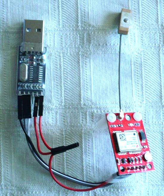
You need a USB to TTL Serial converter. The one I got on eBay uses a CH340G chip. It isn’t perfect. There is a header jumper for selecting 3.3V or 5V. Mine doesn’t work at 3.3V. No problem, the NEO6MV2 module works on 5V. In order to power it you need to make a simple “Y’ cable so that you can provide +5V to both the CH340G module and the NEO6MV2 module.
Using the U-blox U-Center 2 would take an article all by itself and is beyond the scope of this article. Google “using ublox ucenter 2”.
And now some important words about the NEO6MV2 module.
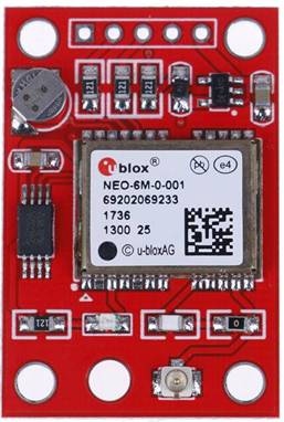
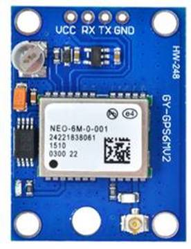
1. There two main versions of the NEO6MV2 module. One uses a Red PCB and the other one uses a Blue PCB. The Red PCB has a 5-pin header. The signals are VCC, GND, TX, RX, and PPS (Pulse Per Second.) The one with Blue PCB has a 4-pin header. GND, VCC, TX, and RX. It does not have the PPS signal on the header. My project needs the PPS signal. The Blue PCB does have a trace where the PPS signal goes to an LED. You could probably adapt the board but it would be some work.
|
NEO6MV2 Red Board - Yes
|
NEO6MV2 Blue Board - NO
|
2. When I started this project all of the NEO6MV2 modules I bought came with an antenna. They are active antennas which means there is a preamp built into the antenna (there is 3.3V on the trace going to the antenna connector).
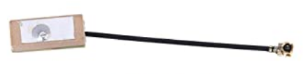
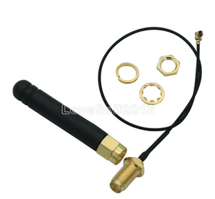
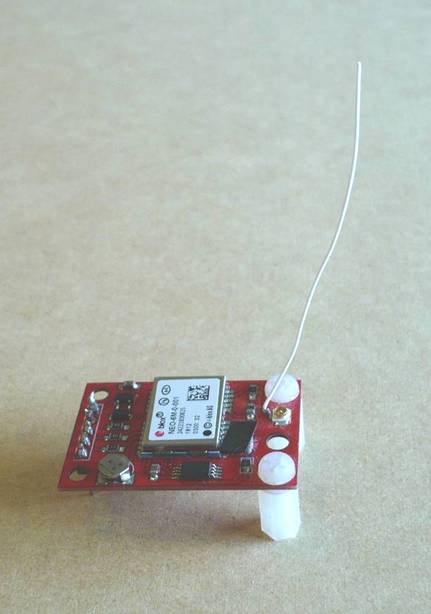
Then I bought some modules and didn’t notice that they were not going to come with antennas. If the picture doesn’t show an antenna then it won’t come with an antenna. You can buy antennas separately. The ones I bought (from Aliexpress) have a thin coax cable with a simple ¼ wave antenna at the end (no preamp). But it can be mounted in a hole so you could put a GPS module in a box and have the antenna outside the box.
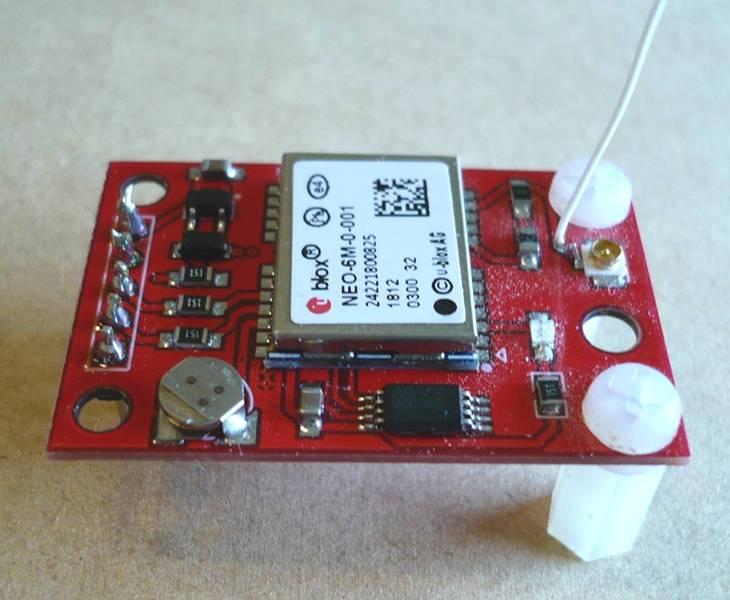
While I was waiting for my antennas I made my own ¼ wave antenna for halfway between the GPS frequencies of 1575.42 MHz, and 1227.6 MHz. It is a piece of #30 Wire-Wrap wire 2 3/8” long. I made the wire 1/16” longer and stripped it there.
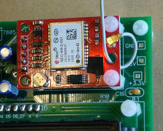
I carefully scraped a small section of solder mask off the trace going to the antenna connector which is a small delicate U.FL connector (also known as I-PEX). https://en.wikipedia.org/wiki/Hirose_U.FL
To make sure I had scraped off all of the solder mask (in that small section) I solder-tinned it. Then I tinned the short exposed piece of my antenna. Then I soldered the end of my wire antenna to the trace.
Soldering the #30 Wire-Wrap wire to the trace requires a soldering iron with a very small tip and using some 0.015” (0.3mm or 0.4mm) diameter solder. I use a USB soldering iron (5V 8W). It has a very small tip.
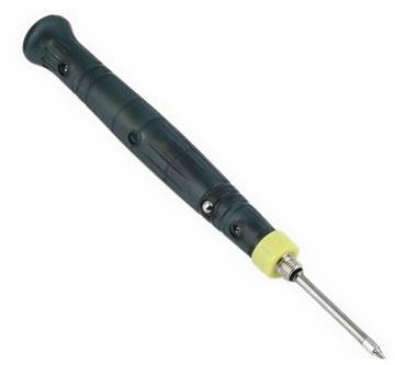
If you plug it into a computer USB port it might not be able to supply enough current. And you should not use a cheap USB power supply. These power supplies use a switching regulator directly off the Mains and can have a leakage voltage of up to 40VAC. The current is very low (tens of microamps) but it is enough to blow the gate of an IGFET (Insulated Gate FET). It could also blow the inputs of an opamp with high impedance inputs. The solution is to use a USB battery pack with nothing else connected to it. And remember to discharge yourself to ground because you might have picked up a charge walking over carpet.
My antenna works almost as well as the active antennas. With the active antennas I typically get 12 satellites in view. With my wire antenna I typically get 11. (And my antenna is cheaper.)
Other Things
1. The U.FL connector is a tiny delicate connector that is rated for only a small of insertions (like 30). Don’t plug it in and out a lot. https://en.wikipedia.org/wiki/Hirose_U.FL
2. The NEO6MV2 module has four mounting holes in the corners. It has an additional hole on one side next to the antenna connector. This hole is so you can thread the antenna cable through it to make a strain relief for the U.FL connector.
3. This is for when you solder the pin header to the module. The ground pin does not use a thermal relief pad in connecting to the ground plane so you have to supply enough heat to heat up the ground plane surrounding the header pin. If you just blob solder onto the header pin it will not connect to the ground plane and the module won’t work.
4. The light from the PPS LED on the module is too bright so I covered it with a small piece of electrical tape. There is enough light from the sides to see it. The light from the backlight for the LCD display spills out the side so I also covered it with a piece of electrical tape.
Files
I am providing the following files:
1. Schematic: jm_gps-clock_schematic.pdf
2. Bill of Material: jm_gps-clock_bom.pdf
3. Source Code:
Clock (MSP430G2553, main.c and main.h): jm_gps-clock-source.zip
Sound (MSP430G2402, main.c): jm_gps-clock-sound-source.zip
The source code is complete. It does not require any libraries other than the ones that come in Code Composer Studio.
4. Gerber files: jm_gps-clock-ra.zip
You can order blank PC Boards from PCBWAY (they will give me a small royalty):
https://www.pcbway.com/project/shareproject/GPS_Clock_and_Armageddon_Alarm.html
Notes
1. To save board space many of the components are under the LCD Display.
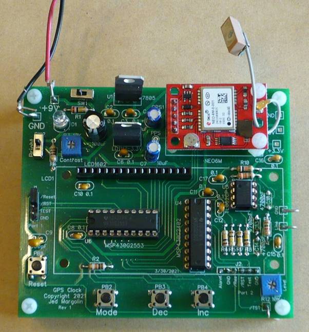
The capacitors you use for C13, C14, and C18 (4700pF Mylar) might not fit under the LCD display. If that is the case you can mount them on the bottom of the board. That is what I did. I also mounted the Launchpad port for the sound processor on the bottom so it wouldn’t get in the way of pressing the pushbutton switch near it.
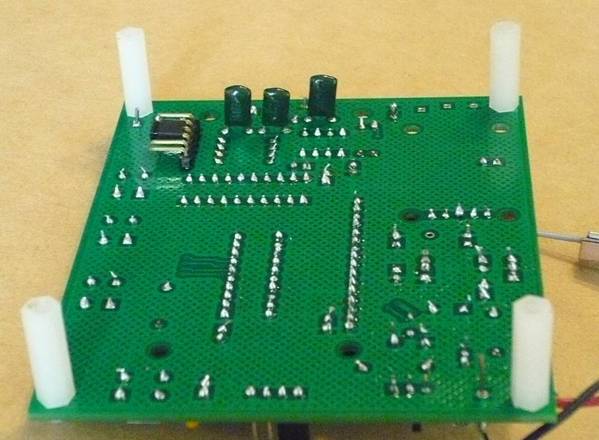
2. The optimum length of the nylon standoffs for the LCD display is 11mm. That is a difficult length to buy. I use 10mm standoffs with a 1mm washer.
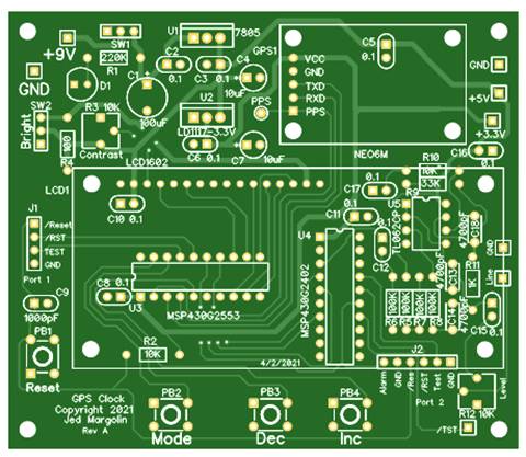
3. This is the bare board top:
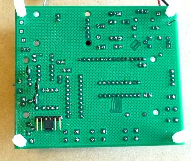
This is the bare board bottom:
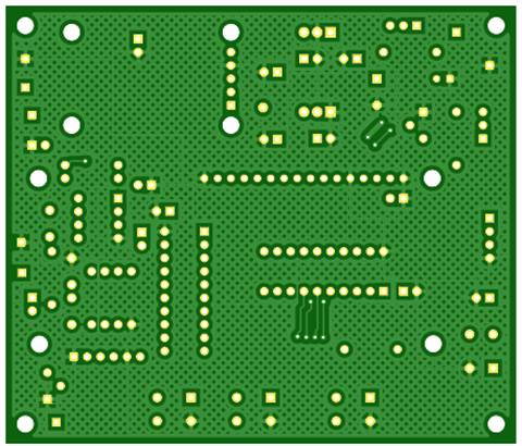
The good ground plane coverage didn’t happen by accident. It certainly didn’t happen by using the auto-router. I routed all of the traces by hand to get good ground plane coverage.
4. I put the ICs in sockets. Always use sockets with machine-tooled pins. The sockets with leaf-springs are crap.
5. When you get the Launchpad, if you want to use it by itself to become familiar with it and Code Composer Studio and you want to use the crystal, you have to jumper the two sets of pads labeled R5 and R7. Here is the MSP-EXP430G2ET User Guide: http://www.ti.com/lit/pdf/slau772.
6. To program the MSG430G2xxx you connect the GPS Clock to the Launchpad with three of these wires: Breadboard Jumper Wires 10cm Dupont Wire, Female to Female.
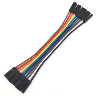
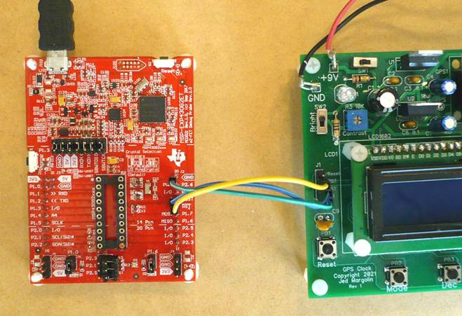
When you use it this way you cannot have a MSP430G2xxx in the Launchpad’s socket, the part is on the GSP Clock Board.
To make it run standalone remove the three wires and use a header plug to connect the /RES and /Reset pins on the header (on the GPS Clock Board).
The sound processor has its own port. This is connected to the Launchpad for programming the MSP430G2402.
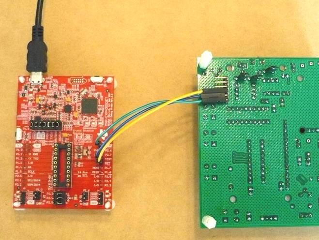
This is standalone mode:
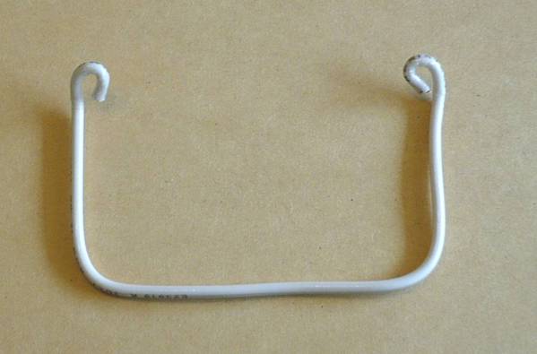
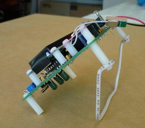
7. I made a simple stand using #12 solid wire. This is the wire used in house wiring.
8. The audio output is Line Level. If you need more or less gain change R9. (Higher = more gain, lower = less gain.)
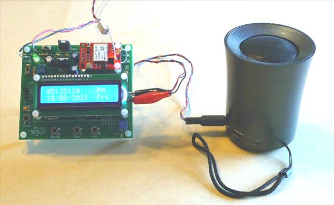
A good (cheap) way to listen to it is with a (cheap) Bluetooth speaker with an Aux input. This one has a rechargeable battery and cost me about $7 on eBay. The Aux input takes a standard 3.5mm stereo miniplug (male).
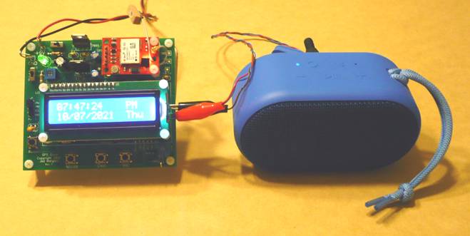
This one is $15 at Walmart. It has a built-in rechargeable battery and sounds remarkably good for being so small and costing so little. The Aux input takes a standard 3.5mm stereo miniplug. And it pairs very easily with Bluetooth masters. Turn the volume all the way up when using the Aux input.
https://www.walmart.com/ip/onn-Small-Rugged-Portable-Bluetooth-Speaker-Cobalt/546646610?athbdg=L1600
If you ground the test pad labeled “/TST” and press the Reset switch the sound processor will play the Armageddon Alarm. It will play it until you unground the /TST pad and press Reset again.
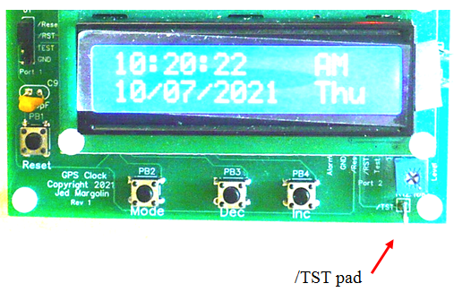
This will not test the Alarm Flag Output, just the sound. I did it this way so you can connect your own alarm without having to stuff the Sound processor.
Do Not Use This Test Function As A Prank.
The End of the World is a serious matter.
Jed Margolin
Virginia City Highlands
Nevada
10/9/2021 Updated 1/2/2022
Update 12/2/2021
From GPS World November 29, 2021:
The Kremlin warned it could blow up 32 GPS satellites with its new anti-satellite technology, ASAT, which it tested Nov. 15 on a retired Soviet Tselina-D satellite, according to numerous news reports.
Russia then claimed on state television that its new ASAT missiles could obliterate NATO satellites and “blind all their missiles, planes and ships, not to mention the ground forces,” said Russian Channel One TV host Dmitry Kiselyov, rendering the West’s GPS-guided missiles useless. “It means that if NATO crosses our red line, it risks losing all 32 of its GPS satellites at once.”
.end