Audio Tone Burst Generator Jed Margolin 10/16/2021
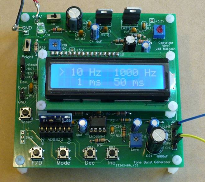
The Audio Tone Burst Generator produces a periodic burst of tone at a User-selected audio frequency at a User-selected repetition rate. It can also be used as a regular audio generator. The frequency range is 20Hz to 10 KHz.
It is used for measuring the time delay of a piece of audio equipment. Modern audio equipment may use some fancy digital processing which may introduce a noticeable delay in the sound. You may want to measure the time delay in a piece of audio equipment in the following situations.
1. If you use your own sound system with your TV and your sound system does some fancy digital processing the delay may be long enough that you will notice that the actor’s mouth movements are not synchronized with the sound. That is very distracting. For television applications, the Advanced Television Systems Committee recommends that audio should lead video by no more than 15 milliseconds and audio should lag video by no more than 45 milliseconds. See https://en.wikipedia.org/wiki/Audio-to-video_synchronization
2. In a sound re-enforcement system such as may be used in a meeting, you can increase the feedback margin by several dB by using a frequency scaler (pitch changer) to change the sound going to the sound re-enforcement system (amplifier and speakers). The sound being fed back is at an ever increasing or decreasing frequency so it doesn’t howl. If you limit the frequency scaling to +/- 5% the people speaking will not notice. Indeed, you should lower the pitch of the person’s voice, not raise it. When we talk, bone-conduction to our ears acts as a low pass filter so our voice sounds lower to us than to the people we are talking to. Thus we are less likely to notice that our speech has been frequency scaled down a little.
The frequency scaler will have some time delay. If delay is more than 50ms we will hear that as an echo and most people will be distracted by that.
Indeed, if the delay is around 200ms most people will try to talk slower (and slower) in order to “catch up” with themselves. This can provide a great deal of amusement for everyone except the person who is talking. The amount of delay depends on several factors including age. See this article on Delayed Auditory Feedback (DAF): https://en.wikipedia.org/wiki/Delayed_Auditory_Feedback. A delay of 200ms seems to be the worst: https://www.ncbi.nlm.nih.gov/pmc/articles/PMC4477042/ .
Frequency scaling is difficult to do in real time.
The best frequency scaler that I have heard is in my old Stanton STR8-80 turntable. It has a control to vary the speed of the turntable and then a frequency scaler (pitch shifter) to restore the pitch of the music. You can speed up and slow down the music without changing its pitch. The turntable also has an auxiliary audio input which is inserted before the pitch shifter. When you use the turntable speed control it obviously cannot change the speed of the auxiliary audio input so you are left with a very fine pitch shifter (frequency scaler).
In measuring the time delay of the Stanton STR8-80 I discovered that the delay is different for different frequencies but in all cases is less than 15ms. This would be a good frequency scaler for a sound re-enforcement system for a meeting.
Some microphone mixers have special effects which include pitch shifters. I have not tested them. If you are using a microphone mixer because you are recording the meeting you want to send the clean mix to the recorder and the frequency-scaled mix to the amp and speakers.
Perhaps a good realtime frequency scaler can be done with a Raspberry Pi.
If so, you can use the Audio Tone Burst Generator to make sure the delay is within an acceptable limit.
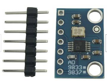
The Audio Tone Burst Generator uses an MSP430G2402 microcontroller to control an Analog Devices AD9833 and displays the User selections on a 16x2 LCD. From the AD9833 datasheet (https://www.analog.com/media/en/technical-documentation/data-sheets/AD9833.pdf):
The AD9833 is a low power, programmable waveform generator capable of producing sine, triangular, and square wave outputs. Waveform generation is required in various types of sensing, actuation, and time domain reflectometry (TDR) applications. The output frequency and phase are software programmable, allowing easy tuning. No external components are needed. The frequency registers are 28 bits wide: with a 25 MHz clock rate, resolution of 0.1 Hz can be achieved; with a 1 MHz clock rate, the AD9833 can be tuned to 0.004 Hz resolution.
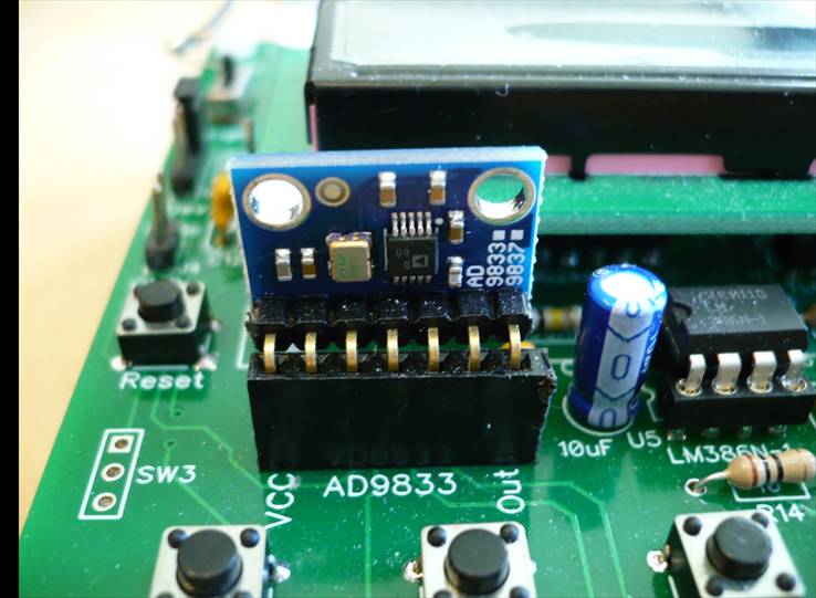
When you buy a module it will probably come with a straight header.
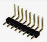
My board layout requires that you use a right-angle header.
This is how to use the Audio Tone Burst Generator.
F/D Switch: Switch between Burst, Frequency, and Sweep Modes;
Press and hold for about 2 seconds (then release) to change modes; Comes up in Burst Mode
In Burst Mode:
INC - Press and release to increase the time between bursts
- Press and hold for about 2 seconds to keep increasing the time between bursts; release to stop
DEC - Press and release to decrement the time Between bursts
- Press and hold for about 2 seconds to keep decreasing the time between bursts; release to stop
MODE - Press and release to toggle the time step between bursts to either 1 ms or 10 ms
In Frequency Mode:
INC - Press and release to increase the frequency
- Press and hold for about 2 seconds to keep increasing the frequency; release to stop
DEC - Press and release to decrement the frequency
- Press and hold for about 2 seconds to keep decreasing the frequency; release to stop
MODE - Press and release to select the frequency steps of 1 Hz, 10 Hz, and 100 Hz
In Sweep Mode: It sweeps between 20Hz and 10KHz until you press and hold the F/D switch.
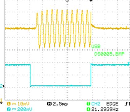
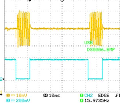
The Header pin labeled “Sync” is for triggering an oscilloscope to measure the delay through the equipment you are testing. In Burst Mode it goes low at the beginning of the burst and goes high at the end of the burst. In Sweep mode it goes low at the beginning of the sweep (20 Hz) and goes high at 1KHz (about 800 ms). The sweep from 20 Hz to 10KHz takes about 8 seconds.
The skill level for stuffing the board is: Intermediate. Make sure you use a temperature-controlled soldering iron. I use a temperature of 340 degrees Celsius. And don’t inhale the solder fumes. If you don’t have a fume hood use a fan to blow the solder fumes away from you.
To compile the source code and download it into the microcontrollers I use Texas Instruments Code Composer Studio. It is free and is on this page:
https://www.ti.com/tool/MSP-EXP430G2ET where you can get the versions for Windows, Linux and macOS.
The direct link to the current version for Windows is: https://software-dl.ti.com/ccs/esd/CCSv10/CCS_10_4_0/exports/CCS10.4.0.00006_win64.zip .
The skill level to use Code Composer Studio is: Advanced. (Maybe Really Advanced).
Files
I am providing the following files:
1. Schematic: jm_tone-burst_schematic.pdf
2. Bill of Material: jm_tone-burst_bom.pdf
3. Source Code: (main.c and main.h): jm_tone-burst-source-v2.zip
The source code is complete. It does not require any libraries other than the ones that come in Code Composer Studio. This is Version 2. Version 1 did frequency steps of only 10 Hz and 100 Hz.
4. Gerber files: jm_gen9833r3.zip
You can order blank PC Boards from PCBWAY (they will give me a small royalty):
https://www.pcbway.com/project/shareproject/Audio_Tone_Burst_Generator_1.html
Notes
1. Before you insert the ICs adjust R4 to produce +3.30V at the test pad. Then put a dab of red nail polish on it. You will still be able to adjust it but it will serve as a warning. Don’t adjust this pot unless:
a. You are sure this is the pot you want to adjust; and
b. You have a reason for adjusting it.
If you are using an ancient Launchpad (that operates at 3.6V) you should adjust R4 for 3.60V.
2. Trimpot R19 adjusts the contrast for the LCD Display.
3. The optimum length of the nylon standoffs for the LCD display is 11mm. That is a difficult length to buy. I use 10mm standoffs with a 1mm washer.
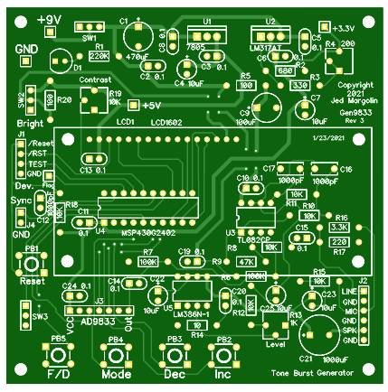
4. This is the bare board top:
This is the bare board bottom:
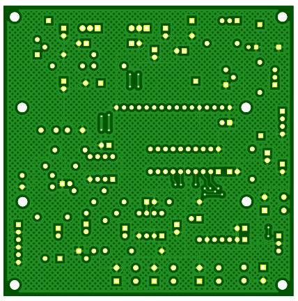
The good ground plane coverage didn’t happen by accident. It certainly didn’t happen by using the auto-router. I routed all of the traces by hand to get good ground plane coverage.
5. To use board space efficiently I put parts under the LCD Display.
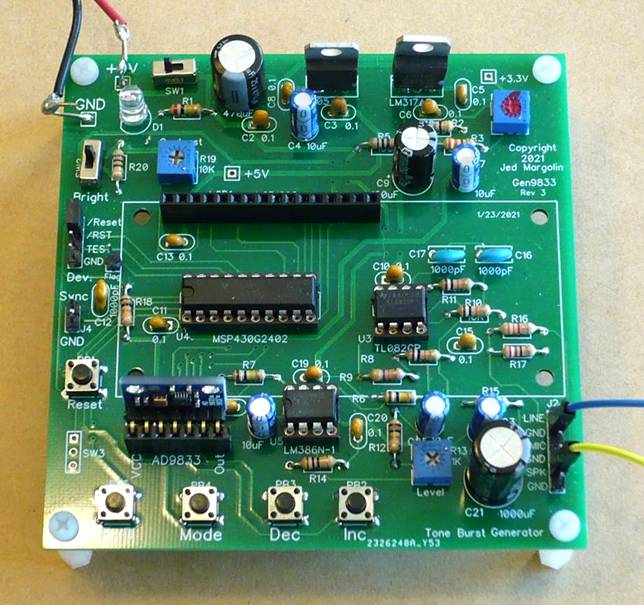
6. I put the ICs in sockets. Always use sockets with machine-tooled pins. The sockets with leaf-springs are crap.
7. When you get the Launchpad, if you want to use it by itself to become familiar with it and Code Composer Studio and you want to use the crystal, you have to jumper the two sets of pads labeled R5 and R7. Here is the MSP-EXP430G2ET User Guide: http://www.ti.com/lit/pdf/slau772.
8. To program the MSG430G2402 you connect the Tone Burst Generator to the Launchpad with three of these wires: Breadboard Jumper Wires 10cm Dupont Wire, Female to Female.
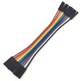
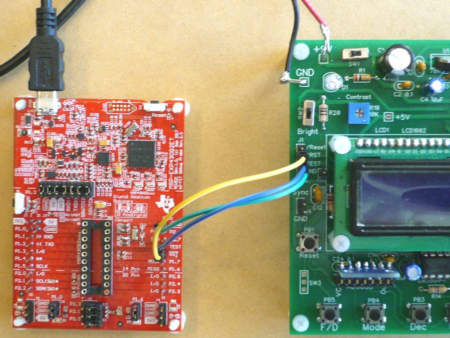
When you use it this way you cannot have a MSP430G2xxx in the Launchpad’s socket. The part is on the Tone Burst Generator Board.
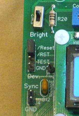
To make it run standalone remove the three wires and use a header plug to connect the /RES and /Reset pins on the header (on the Tone Burst Board).
9. The audio outputs are: Line Level, Microphone Level, and Speaker. The Speaker output does not produce much power. It is there so you can listen to the Generator when you are using it. If the Line and Mic outputs are not exactly the levels that you need you can change R15, R15, and/or R17.
Happy Tone Bursting.
Jed Margolin
Virginia City Highlands
Nevada
10/16/2021 Updated 1/2/2022, 3/11/2022
.end