Analysis of Art for U.S. Patent 5,566,073
Pilot aid using a synthetic environment
Jed Margolin
A number of references have recently been cited as
constituting prior art to invalidate U.S. Patent
5,566,073
Pilot aid
using a synthetic environment issued October 15, 1996 ('073).
This report analyzes
these references and shows that they do not anticipate '073.
Index
I. Introduction
II. Additional References
A.
Microsoft Flight
Simulator
B. DGLR Report 92-02 Advanced Display Systems for
Aircraft,
Vehicles, and Process Control 34. Technical Committee Meeting September
24-25 Munich, BMW AG.
C. U.S. Patent 4,660,157
Real time video perspective digital map display method
issued
April 21, 1987 to Beckwith, et al.
D. U.S.
Patent 4,682,160
Real time perspective display employing digital map generator
issued
July 21, 1987 to
Beckwith, Jr., et al.
E. U.S.
Patent 5,179,638
Method and apparatus for generating a texture mapped perspective view
issued
January 12, 1993 to Dawson, et al.
F.
European Patent
Application EPO 0 399 670, Airborne
computer generated image display systems filed April 27, 1990 by
Schofield and O'Leary (British Aerospace)
In order to invalidate a
U.S. patent a reference must show that the inventor of the patent was
not the first to invent the claimed invention.
1.
The first requirement is that all of the elements of the independent
claims are present in the reference. If even one element is
missing from the reference, then the claim survives. If all of the
independent claims are anticipated then the patent is completely
invalid. If only some independent claims are anticipated then the
remaining ones remain valid.
The '073 patent has four
independent claims: Claims 1, 12, 23, and 29. For the purposes of this
analysis only claim 1 needs to be considered.
1.
A pilot aid which uses an aircraft's
position and attitude to transform data from a digital data base to
present a pilot with a synthesized three dimensional projected view of
the world comprising:
a position determining system for locating said aircraft's position in
three dimensions;
a digital data base comprising terrain data, said terrain data
representing real terrestrial terrain as at least one polygon, said
terrain data generated from elevation data of said real terrestrial
terrain;
an attitude determining system for determining said aircraft's
orientation in three dimensional space;
a computer to access said terrain
data according to said aircraft's position and to transform said terrain data to
provide three dimensional projected image data according to said aircraft's
orientation; and
a display for
displaying said three dimensional projected image data.
The full '073 patent
is contained in 5566073.pdf .
2. Because the reference must show that the
inventor of the patent was not the first to invent the claimed invention, dates
are important.
The important
date for the patent is the date of "reduction to practice." This can be either
when an actual invention was constructed and the claimed invention worked for
its intended purpose or when a properly executed patent application was
filed.
The '073 application
was filed August 9, 1995 but was a continuation of an application filed on Jul.
11, 1994. For the purposes of this analysis the date of July 11, 1994 can be considered the
date of "reduction to practice."
The important date for the reference cited against the
patent can be complicated. For a non-patent reference it can be considered the
date of publication. For a patent reference it must be the date of reduction to
practice. This can be the date of the application (which is easy to show) or the
date the invention was constructed and worked for its intended purpose (which is
not easy to show and requires documentation such as inventors' notebooks.)
For the purposes of this analysis it will be sufficient to
use the application date of patent references and the publication date of
non-patent references unless the non-patent reference is the history of a device
or product. In that case the history of the device or product will be further
investigated.
3. The question will arise, "Is a Digital
Terrain Elevation Database Really a Polygon Database?"
The
short answer is, "If a Digital Terrain Elevation Database (DTED) is used to
produce polygons, then it is a polygon database."
This is explained more fully in the report Is a Digital Terrain Elevation Database (DTED) really a
Polygon Database? which is incorporated herein by reference.
4. Words may change meaning or may acquire
additional meanings over time. It is nice when a term is explicitly defined but
this is not always the case. A term used in an old reference must be given the
meaning it had when it was used. Technically, a term must be given the meaning
it had to a Person Having Ordinary Skill in the Art (POSITA) at the time it was
used. It is not permitted to read into a term the meanings it acquired later due
to advances in the technology. The art in this case is Airborne Computer
Graphics Image (ACGI) Systems, which have severe space and power constraints
compared to their ground-based counterparts.
II. Prior Art References
A. Microsoft Flight Simulator: (Flight
Simulator 5.1 Screen Shot.pdf and Flight Simulator
History.pdf .)
Flight Simulator 5.1 was released in 1995. The '073 patent
has a priority date of July 11, 1994.
In addition, the
Microsoft Flight Simulator did not start using 3D terrain until Flight Simulator
2000 Pro, released in late 1999.
From: http://www.flightsim.com/cgi/kds?$=main/review/fs2000.htm (reproduced here)
GRAPHICS
We now have another complete globe to fly around. With the
new mesh style scenery we have real elevation points that make the surrounding
terrain rise and fall like the real earth. We have no more flat areas that just
pop up into place at the last minute during a landing
approach!
Even then, it is not clear if the terrain database
represents real terrain or is made up.
The article mentions
the new GPS feature:
737 Panel
The 737-400 panel is very
nicely done. Simple, yet effective. This is where FS2000 is not much different
than FS98. However, the overall clarity, coloring, detailing and some new
systems make it much better. We now have nice popups for the throttle quadrant,
radio stack, compass and best of all the new GPS.
The GPS is part of the
737 control panel. There is no suggestion that a physical GPS unit can be
connected to the program.
Therefore, none of the versions of the Microsoft Flight
Simulator anticipate '073.
B. DGLR Report 92-02 Advanced Display Systems for Aircraft, Vehicles, and
Process Control, 34. Technical Committee Meeting September 24-25 Munich,
BMW AG., Deutsche Gesellschaft fur Luft -und Raumfahrt e.V. (The German Society
for Air and Space) and Forschungsinstitut fur Antropotechnik der FGAN e.V.
(Research Institute for Ergonomics) (Advanced
Displays Article.pdf)
1. It does not show: "a position determining system for
locating said aircraft's position in three dimensions;".
2. It does not show: "an attitude determining system
for determining said aircraft's orientation in three dimensional space;
".
3. It does not do real-time graphics.
From "4 Realization
aspects" page 180:
The illustrations shown here
were realized on an IBM PC (386/33 MHz) with a VGA graphics card (640 x 480
pixels, 16 colors). The programming language used was Turbo-Pascal. This
development environment has the advantage of fast implementation in terms of
rapid prototyping which appears especially important for the graphic
visualizations. However, real-time capabilities cannot be expected due to the
limited processing power of a PC.
The real-time aspect was investigated in an additional
implementation on a graphic workstation from Silicon Graphics Inc. in
conjunction with a flight simulator. In summary, in can be said that this
computer also fails during concurrent use of several of the functions/display
described. However, the software was not optimized for runtime.
4. Most of the illustrations are of maps. An
illustration that may show a 3D image is the upper image in Illustration 9.
However, it states "Illustration 9: Simple perspective view as visibility aid
for display overlay." Earlier, Illustration 6 is also characterized as a "simple
perspective display.." but adds that it is a "cavalier display." The text
clarifies it as a "cavalier perspective". (Page 175 Section 2.5) Cavalier
Perspective is not a true 3D projection.
From http://en.wikipedia.org/wiki/Cavalier_perspective:
The
cavalier perspective, also
called
cavalier projection or
high view point, is a way to represent a three
dimensional object on a flat drawing, and more specifically, a type of
oblique projection.
A point of the object is represented by three coordinates,
x, y and z. On the drawing, it is represented by only two
coordinates, x" and y".
On the flat drawing, two axes, x and z on the figure, are perpendicular and the length on
these axes are drawn with a 1:1 scale; it is thus similar to the dimetric
projections, although it is not an orthographic projection, as the third axis,
here y, is drawn in diagonal, making an arbitrary
angle with the x" axis, usually 30 or 45°. The
length of the third axis is not scaled[1][2].
It is very easy to draw, especially with pen and paper. It
is thus often used when a figure must be drawn by hand, e.g. on a black board
(lesson, oral examination).
The full Wikipedia
entry is reproduced here.
As result, at most this article describes only a simulator,
and not even a real-time simulator. It does not describe a pilot aid which uses
an aircraft's position and attitude to transform data from a digital data base
to present a pilot with a synthesized three dimensional projected view of the
world.
C. U.S.
Patent 4,660,157 Real
time video perspective digital map display method issued April 21, 1987 to
Beckwith, et al. (4660157.pdf)
U.S. Patent 4,660,157
is listed on the front page of '073 as a reference. (fp_073)
It was considered by
the Examiner. (xids1 and xids2)
In the EXAMINER'S STATEMENT OF
REASONS FOR ALLOWANCE he said:
II. This communication is an Examiner's
reasons for allowance in response to application filed on August 09, 1995,
assigned serial 08/513,298 and titled "PILOT AIDED USING SYNTHETIC REALITY".
III. The
following is an Examiner's statement of reasons for the indication of allowable
subject matter:
1. After carefully reviewing the
application in light of the prior art of record, the amended claims and
additional search of all the possible areas relevant to the present application
a set of related prior art have been found, but those prior art references are
not deemed strong to make the application unpatentable. Thus, it is found that
the application is now in condition for allowance.
2. Although the prior art disclose
several claimed limitations, none of the references teach a pilot aid which uses
an aircraft's position and attitude to transform data from a digital data base
to present a pilot with a synthesized three dimensional projected view of the
world which includes a digital data base comprising terrain data representing
real terrestrial terrain as at least one polygon and said terrain data generated
from elevation data of the real terrestrial terrain (claims 1, 7, 13 and 36).
3. The closest
references have been found were Beckwith et al., Behensky et al., Ulrich ,
Jacobs et al., Raymer et al., Patrick. However, taken individually or in
combination, they do not teach or make obvious a polygon database representing
real terrestrial terrain where that polygon database was generated from
elevation data of real terrestrial terrain.
4. Claims 1-28 and 31-39 are allowable
over the prior art of record (now renumbered as 1-37).
Nonetheless, the following is an analysis of Beckwith
'157.
Instead of
mathematically rotating the points from the database the '157 Patent accounts
for the aircraft's heading by controlling the way the data is read out from the
scene memory. Different heading angles result in the data being read from a
different sequence of addresses.
From Column 3, lines 21 - 38:
The addresses of the elevation data read out of the scene
memory representing points in the two-dimensional scene of the terrain are then
transformed to relocate the points to positions where they would appear in a
perspective scene of the terrain. Thus, each point in the two-dimensional scene is
transformed to its new location in the perspective scene to be displayed on the
viewing screen, and in the process, the data is automatically oriented
with a heading-up disposition. The transformed points are then stored in a speed
buffer for further processing by sun angle and line writing logic prior to being
stored in a display memory from which data is read out to the display screen.
Since data in the display memory represents one-to-one data to be displayed on
the CRT, this data will be referred to as pixels (picture elements) in terms of
its storage in the display memory for transfer to the CRT display.
Emphasis added to show that '157 displays only points. It
does not display polygons. Although that makes further analysis unnecessary, for
the sake of completeness we will continue.
Beckwith's figures
show:
FIG. 5 is a schematic
diagram illustrating the starting point calculation and scanning as applied to
the scene memory;
FIG.
6 is a
schematic block diagram of the X-scanning portion of the scan control for the
scene memory;
FIGS.
7a-7h are
schematic diagrams which illustrate the various scanning directions and selected
starting points based on aircraft heading;
Beckwith '157 uses a
transformation for creating perspective for the points. From Column 3, lines 21
- 29:
The addresses of the elevation data read out of the scene
memory representing points in the two-dimensional scene of the terrain are then
transformed to relocate the points to positions where they would appear in a
perspective scene of the terrain. Thus, each point in the two-dimensional scene
is transformed to its new location in the perspective scene to be displayed on
the viewing screen, and in the process, the data is automatically oriented with
a heading-up disposition.
The '157 patent
accounts for the roll attitude of the aircraft by mathematically rotating the
screen data after it is projected. From Column 12, lines 42 - 47:
The points which are output by the perspective transform
circuit 110 are supplied to a screen rotation circuit 120 which serves to rotate
the display data in accordance with the roll of the aircraft so that the display
will accurately depict the view as it would appear, if visible, through the
window of the aircraft.
This emphasizes that
only points are displayed, not polygons, and therefore the '156 database is not
a polygon database.
D. U.S. Patent 4,682,160 Real time perspective display
employing digital map generator issued July 21, 1987 to
Beckwith, Jr., et al. (4682160.pdf)
The usual method for
displaying a 3D database is to use the Observer's position to get the
appropriate data from the database, transform the data according to the
Observer's position and orientation, and project the result onto the display
screen. Nowadays, most displays are of the raster-scan type and frame buffers
are used. In a frame buffer each location in the frame buffer memory represents
a pixel on the screen, so the frame buffer must contain enough memory to
represent each pixel. After the frame buffer memory is filled with all the
pixels to be displayed during the frame, the frame buffer memory is read out in
synchronization with the display's scanning rate. Typically, the frame buffer
contains enough memory to display two display frames (two buffers) so that one
buffer is filled while the other is displayed. Then the two buffers are
switched. (It's called the ping-pong method.)
Beckwith '160 does
something very different.
Beckwith starts by using the Observer's position to
establish rays to a selected vertical line in the display. (See Figure 1 and Figure 2)
He then uses Angle
Processor 31 to determine which elevation points in the terrain database might
end up on that line.(See Figure 6)
Somehow (it's not very
clear) the projected heights of the elevation points (Scene Memory 41) are
determined and written into a Line Buffer using Pixel Address Calc.
63.
The Line Buffer
represents a vertical line on the screen. Since most monitors are scanned
horizontally the monitor must be physically rotated 90 degrees to make the line
vertical. (Column 2, lines 54 - 58)
As normal CRT screen beam
scanning is horizontal across the target faceplate, a simple 90.degree. rotation
of the display accomplishes alignment of the CRT sweep lines with the data as
written in and read-out of the line buffers.
The reason for using a
line buffer is because a line buffer only needs enough memory to store one line
of pixels (in this case 512 pixels) instead of the entire frame (512 x 512 =
262,144 pixels).
Note that two line buffers are used so that one is filled
while the other is being scanned out to the display (the ping-pong method, see
Figure 15).
At the time the
invention taught by Beckwith '160 was made (July 1983), memory was much more
expensive than it is today and, since frame buffers use a great deal of memory,
they were very expensive.
The use of line buffers reduces the cost of the hardware
substantially.
Beckwith teaches other features such as a Brightness
Calculation (Brightness Calc 71) according to a Sun Angle and rotating the
displayed image to account for the roll angle of the aircraft.
Beckwith also states
that a frame buffer may be used instead of a line buffer so that the monitor
does not need to be physically rotated 90 degrees.
However, the end
result of all this is that Beckwith writes only points on the display. He does
not display polygons. Therefore, his digital elevation database is not a polygon
database and Beckwith '160 does not anticipate '073.
As a side note.
Beckwith was not the first to use a line buffer to avoid the expense of a frame
buffer.
Atari was.
U.S. Patent
4,116,444
Method for generating a plurality of moving objects on a
video display screen issued September 26, 1978 to Mayer et al. (filed
July 16, 1976) shows the use of a line buffer (called a horizontal memory) to
allow a number of motion objects to be displayed.
During horizontal blanking the list of motion objects is
scanned and if any of them have parts of them (lines) that are supposed to be
displayed on the next horizontal line, then that line from the motion object is
written into the horizontal memory at the proper place.
There is a subtle limitation of
this method. While it allows a large number of motion objects to be displayed on
the screen there is a limitation of how many objects can be displayed on the
same line. This is a limitation that Game Programmers always had to deal with.
This basic method (which
evolved over time to allow more and more motion objects to be displayed) was
used in all of Atari's coin-operated video games except for games like
Asteroids, BattleZone, and Star Wars (which used Random-Scan monitors and custom
vector generators to drive the displays) and a number of games that did use
frame buffers. Missile Command was an early game that used a frame buffer (1981)
and most of the 3D simulator games like Hard Drivin' (1988),
Race Drivin'
(1990), Steel Talons (1991), and used
frame buffers, but Atari (by then called Atari Games) continued to use the line
buffer method in many of its games until the final end of the company in 1996
when it was sold to WMS Industries.
E. U.S. Patent 5,179,638 Method and apparatus for
generating a texture mapped perspective view issued January 12, 1993 to
Dawson, et al. (5179638.pdf)
U.S. Patent 5,179,638 is listed on the front page of '073
as a reference. (fp_073)
It was initialed by
the Examiner on the PTO-1449. (xids1)
In the Office Action dated May 4, 1995 the
Examiner stated (page 9 section 11):
11.
The following references are cited as being of general interest: Sullivan et al.
(4,213;252), Heartz (4,715,005), Dawson et al. (5,179,638) and Nack et al.
(5,317,689).
Thus, the Examiner considered the Dawson patent and found
it of only general interest. It was not cited as relevant to '073.
Nonetheless, the following is an
analysis of Dawson '638.
Dawson
'638 uses the right words: Aircraft, Digital Terrain Elevation Database (DTED),
Polygons, Transformation, Perspective. But he does not anticipate '073.
Here's why.
Dawson uses the DTED to create 3D
polygons. He transforms the polygons. He maps a texture onto the 3D polygons
using a texture such as from aerial reconnaissance photographs. He
creates a perspective view of the polygons and displays them.
But.
His perspective view is not a 3D projected view and, more
importantly, it is not responsive to the aircraft's Roll and Pitch angles
relative to the ground.
From Column 2, lines 21 -
45:
The invention provides a
texture mapped perspective view architecture which addresses the need for
increased aircraft crew effectiveness, consequently reducing workload, in low
altitude flight regimes characterized by the simultaneous requirement to avoid
certain terrain and threats. The particular emphasis of the invention is to
increase crew situational awareness. Crew situational awareness has been increased to some
degree through the addition of a perspective view map display to a plan view
capability which already exists in digital map systems. See, for example,
assignee's copending application Ser. No. 07/192,798, for a DIGITAL MAP SYSTEM,
filed May 11, 1988, issued Oct. 24, 1989 as U.S. Pat. No. 4,876,651 which is
incorporated herein by reference in its entirety. The present invention
improves the digital map system capability by providing a means for overlaying
aerial reconnaissance photographs over the computer generated three dimensional
terrain image resulting in a one-to-one correspondence from the digital map
image to the real world. In this way the invention provides visually
realistic cues which augment the informational display of such a computer
generated terrain image. Using these cues an aircraft crew can rapidly make a
correlation between the display and the real world.
Emphasis added.
Let's look at the
statement:
Crew situational awareness
has been increased to some degree through the addition of a perspective view map
display to a plan view capability which already exists in digital map systems.
See, for example, assignee's copending application Ser. No. 07/192,798, for a
DIGITAL MAP SYSTEM, filed May 11, 1988, issued Oct. 24, 1989 as U.S. Pat. No.
4,876,651 which is incorporated herein by reference in its entirety.
What already exists? Does
Dawson '651 provide "a perspective view map display" or does it only provide "a
plan view capability?"
Adding
"a perspective view map display" only increases crew situational awareness "to
some degree" which is why:
The present invention
improves the digital map system capability by providing a means for overlaying
aerial reconnaissance photographs over the computer generated three dimensional
terrain image resulting in a one-to-one correspondence from the digital map
image to the real world.
This strongly suggests that Dawson '651 provides "a
perspective view map."
Let's look at the
"perspective view map display" taught by '651. (Here is Dawson 4,876,651)
In the '651 section on prior art,
Dawson describes the difficulties of using paper maps. From Column 1, lines 20 -
23:
While paper maps can provide topographical features of the
terrain, it poses a large burden on the pilot to try to calibrate the aircraft's
position from a paper map on the pilot's knee.
He then equates a digital map to an electronic version of a
paper map. From Column 1, lines 23 -28:
A digital map system
electronically generates a map similar to the format of a paper map. It is
desirable that such a display automatically calibrate the aircraft's position,
show terrain elevation, and cultural and linear features such as roads,
railroads, and rivers.
After describing the deficiencies of existing systems he
states (Column 1, lines 50 - 60)
The present invention
overcomes the disadvantages of the wrap-around storage system and the check
point navigational system, both of which are slow in accessing data and updating
memory, therefore rendering real time displays difficult The present invention
provides an improved virtual memory storage and access technique for providing a
real time display which permits overlaying data such as character symbology,
contour lines, and dynamic sun angle shading in addition to the terrain data and
for decluttering by selecting or deselecting individual features from the map
for display.
It would be
useful to show you a paper map. Unfortunately, I cannot show you an actual paper
map unless you come to my house. (Please call ahead for directions, a discussion
of what kind of vehicle you will need, and why getting to my house can be a real
challenge at any time of year, especially Winter.)
The next best thing is to electronically scan a paper map
and make an electronic version of it.
Here is a part of the Washington Sectional Aeronautical
Chart, Scale 1:500,000 55th Edition, published March 3, 1994 by U.S. Department
of Commerce National Oceanic and Atmospheric Administration National Ocean
Service. Click Here for map PDF. If you are not
familiar with the symbology used in paper sectional maps here is the Washington Legend.
If you use the Zoom and Pan
features of Acrobat you will see the advantages of an electronic version of a
paper map (i.e., a digital map).
You will also see that Dawson's digital map is not an
aerial reconnaissance photograph nor is it derived from a Digital Terrain
Elevation Database.
What does
Dawson '651 do?
Column 2, lines
3 - 38:
The digital mapping
display system for use in an aircraft includes a mission computer for generating
digital signals indicative of the aircraft's present longitude and latitude
coordinate positions, a heading signal indicative of the angular direction of
motion, and signals corresponding to map data cultural features and graphical
data, a mass memory unit for storing map data signals in digital form which
represent a map of the territory overflown by the aircraft and which provide map
data signals corresponding thereto, and for storing overlay data in digital form
representative of graphical information to be superposed on the map data and for
providing overlay data signals corresponding thereto. In the preferred
embodiment, the mass memory unit is coupled to a mass data controller which
extracts map data or overlay data in accordance with the aircraft trajectory and
periodically updates the stored images. A cache memory is coupled to the data
controller for electronically storing digital images which are indicative of
portions of the map of territory overflown by and surrounding the aircraft and
the graphical images overlaying these areas. The cache memory includes a
plurality of randomly programmable segmented buffer elements arranged in a
virtual memory array for storing and dynamically relocating portions of the map
data with respect to changes in the aircraft's coordinate position. Control
signals from a control processor write data and refresh portions of the cache
memory while simultaneously reading data out from other portions. The control
processor receives signals generated by the mission computer for periodically
updating the cache memory as the aircraft's coordinate position changes. The
mass memory unit is periodically accessed to update the cache memory as the
aircraft reaches the boundaries of the prestored information.
Column 12 line 58 - Column 12 line 28:
Referring now to FIG. 8, the
structural details of the address generator 192 are shown in greater detail.
Address signals from display stream manager 52 are applied to a decoder 210 via
a bus 212. Decoder
210 provides output commands such as initialization of the initial x and y
coordinate starting points, aircraft heading, zoom ratio, and initial x and y
line count. The address generator consists essentially of four function
blocks: a read address generator 212, a write address generator 214, x and y
line counters 216 and a state sequencer 218. Coordinate translation coefficients
to provide an upper left justified coordinate system within the absolute cache
address space and rotation coefficients corresponding to the aircraft heading
are provided by circuit 220. These functions may also be provided by the general
purpose processor if desired. The commands from decoder 210 are coupled to read
address generator 212 and write address generator 214 on bus 216. Further
commands to state sequencer 218 are applied on line 222. Line counter 216
receives its initialization commands on bus 224. Functional block 220,
which may comprise sine and cosine memories to scale the sine and cosine values
provides the computed address parameters to read address generator 212 and write
address generator 214 on bus 226. Control signals from state sequencer
218 are applied to read address generator 212 via bus 228 and to write address
generator 214 via bus 230. Line counter 216 is coupled to controller 218 via
busses 232 and 234. Controller 218 also provides read and write clocks and
control signals to the scene memory, video processor, and overlay processor. The
output of read address generator 212 is applied to the cache memory 194 and
video processor 196 via bus 201. Write address generator 214 provides a write
address via bus 205 to scene memory 198 and overlay processor 208. The control
processor provides data signals via bus 236 to counter 217, state sequencer 218,
function block 220, read address generator 212, and write address generator 214.
Column 13, lines 29 -
61
Operation of the address
generator may be more clearly understood by reference to FIG. 9a, FIG. 9b, and
FIG. 9c, with continued reference to FIG. 8. At the start of each update
cycle, the address generator, which receives its control parameters from the
display stream manager through the decoder 210, is commanded to perform a
display list scan. Typically, nine consecutive 910 byte display lists filling a
maximum of 8192 bytes will be transferred to the overlay processor in this mode.
The lists are transferred consecutively and hence written in consecutive
locations in the overlay processor. A starting address provided by the display
stream manager provides a segment tag to the overlay processor which will
identify the display list to be transferred with its associated buffer segment.
After the segment
tag has been given to the overlay processor, the address generator then
generates the read and write addresses to transfer the display list information
from the cache memory to the overlay memory 44. The read address generators 212
are basically arithmetic logic units which perform a series of incremental adds
after receiving a starting point, pixel-to-pixel increment values, and
line-to-line increment values from the function block 220. The initial x and y
starting points are calculated by the display stream manager using a normalized
coordinate system and the aircraft heading information. These initial values are
then loaded into the respective x and y address generation circuits. Aircraft
heading and zoom information is also provided to the address generator through
data bus 236. Function block 220 comprises addressable sine/cosine prom's which
determine the direction from the starting point and the increment for each
repetitive add operation.
It stores a digital map and
displays it according to the aircraft's position and heading.
The map is stored in a North-up
orientation. The method used to rotate the map to the aircraft's heading is to
control the sequence used to read the map data from the cache. Different heading
angles result in the data being read from a different sequence of addresses.
Since addresses exist only at discrete locations, the truncation of address
locations causes an unavoidable change in the map shapes as the aircraft changes
heading.
According to Dawson,
"Operation of the address generator may be more clearly understood by reference
to FIG. 9a, FIG. 9b, and FIG. 9c, with continued reference to FIG. 8."
Unfortunately, there are no
figures FIG 9a, FIG. 9b, and FIG 9C. There is a FIG. 9 but it is not relevant to
this text.
Reference is made
later on to U.S. Patent 4,884,220 Address generator with variable scan patterns
(issued November 28, 1989 to Dawson, et al.) but it does not explain
the principle of how it works.
So, here is the general principle.
We start with point (X,Y) on a 2D
Cartesian coordinate grid (Rfig. 1). We want to rotate the point around the
origin by angle a.
The new coordinates of point (X,Y) will be (X',Y'). (Rfig. 2)
This is accomplished by performing the following
equation:
X' = X * cos(a)
- Y * sin(a)
EQUATION 1
Y' = X * sin(a)
+ Y * cos(a)
This
requires two multiplies and two additions.
At the time of the Dawson invention, multiplies were
expensive either in time or hardware cost.
A multiply is simply a repeated addition, so that in the
case of A*B you can just add A, B times (A + A + A + ...).
Here is how this fundamental
definition of multiplication can be used to rotate a digital map.
A digital map is read into a
two-dimensional memory array. Each memory location contains the intensity of the
pixel. In the following figure RFig. 3 no attempt was made to create a realistic
picture so each pixel is just a black dot.
Each pixel is located in a memory location specified by its
X address and its Y address (X,Y).
To copy this picture ("object picture" or just "object") to
a Frame Buffer, start with the pixel in Address(0,0) and write it to the desired
address in the Frame buffer. The starting address in the Frame Buffer determines
where on the screen the picture will be.
The next address to read will be Address(1,0) which is X=1
and Y=0. Write the pixel to the Frame Buffer at Frame Buffer Address X=X+1 and
Y=Y.
Thus, by keeping Y = 0,
and incrementing X from 0 to 5 we can copy the entire first row of the picture
into the Frame Buffer.
Now
increment Y and repeat the next row.
Do this until the entire picture has been transferred to
the Frame Buffer.
We can use
this scanning process to rotate the picture.
The Sine and Cosine PROMs referred to by Dawson contain
Sine and Cosine lookup tables. The input (the address) to the Sine PROM
represents the angle. The Output (the Data) is the Sine of that angle. (Because
we are dealing with integers some scaling is required.) Similarly, with the
Cosine PROM the input (the address) to the Cosine PROM represents the angle and
the Output (the Data) is the Cosine of that angle. (Again, because we are
dealing with integers some scaling is required.)
Equation 1 is, again:
X' = X * cos(a)
- Y * sin(a)
EQUATION 1
Y' = X * sin(a)
+ Y * cos(a)
There
are Accumulators XC, YS, XS, and YC.
The outputs of Accumulators
XC and YS go to a Subtractor whose output is XC - YS = X'.
The outputs of Accumulators XS and YC go to an Adder whose
output is XS + YC = Y'.
There are Counters X and Y.
Start by clearing
Accumulators XC, YS, XS, YC, and Counters X and Y.
1. X' and Y' are used as the address to the picture
array. Read it.
X and Y are used to index the
address in the Frame Buffer. Write it.
2. Increment X, add cos(a) to Accumulator XC and add
sin(a) to Accumulator XS.
X' and Y' are used as the
address to the picture array. Read it.
X and Y are used to index the address in the Frame Buffer.
Write it.
3. Repeat
step 2 until we get to the end of the picture array line.
4. Clear Accumulators XC and
XS and Counter X.
5.
Increment Counter Y, add sin(a) to Accumulator YS, and add cos(a) to Accumulator
YC.
6. Repeat steps 1, 2
and 3 until all the lines in the object picture have been done.
RFig. 4
shows the results of forming the X' and Y' addresses.
Note that these represent addresses. Some of them will be
outside the object picture and some pixels of the object picture will not be
addressed.
The Frame Buffer
addresses are incremented using the non-rotated X and Y addresses (counters).
And that is a cheap way to rotate
a picture as it is transferred to a Frame Buffer. That is the method taught by
Dawson '220 and used by Dawson '651.
There are some problems with
it.
The picture pixels exist at
only discrete addresses. (For example, there is no address X=1.5, Y=3.5)
Dawson deals with it by an
interpolation scheme.
Here is
another way to rotate a picture.
Starting with X=0 and Y=0, read the picture pixels.
Perform Equation 1 on the
addresses using real Multipliers.
The resulting X' and Y' form the Frame Buffer Address.
After appropriate scaling put the
pixel in the Frame Buffer at that address.
In a system where the screen resolution is greater than the
resolution of the object picture there are more (different) addresses to write
the result to, especially when you take scaling into consideration..
For example, the object picture
may be 32 * 32 and the screen resolution may be 1024 * 768.
With, for example, 2:1 scaling
there are twice as many addresses to put the pixels in than existed in the
Object picture array space. In essence, we now do have addresses at X=1.5 and
Y=3.5.
This analysis brings up the following question.
Instead of using Dawson's method
of rotating the addresses of the object picture and stepping through the index
addresses of the Frame Buffer, why not step through the addresses of the object
picture and rotate the index addresses of the Frame Buffer?
That way you do not miss addresses
in the object picture. And, if the Frame Buffer resolution is higher than the
object picture resolution, you might not even need to perform interpolation.
The answer is in U.S. Patent 4,884,220 Address Generation with Variable
Scan Patterns issued November 28, 1989 to Dawson (again), which is
incorporated by reference by Dawson '638. Dawson '220 references Dawson '651 as
Application 07/192,798.
After discussing the
shortcomings of prior art, Dawson '220 says (Column 2, line 56 through Column 3,
line 2):
This invention differs
from the prior methods of perspective view generation in that a trapezoidal scan
pattern is used instead of the radial scan method. The trapezoidal
pattern is generated by an orthographic projection of the truncated view volume
onto the cache memory (terrain data). The radial scan concept is retained, but
used for an intervisibility overlay instead of the perspective view generation.
The radial scan is enhanced to include a full 360 degree arc with programmable
attributes. The rectangular pattern retains the parallel scan methodology for
plan view map generation. Both a nearest neighbor and a full bilinear
interpolation method of scan address generation are implemented.
And now we know what Dawson
means by "perspective."
He
means to squeeze the picture into the shape of a trapezoid so that it become
foreshortened as it approaches one end. This is usually referred to as the
"keystone effect". See: http://en.wikipedia.org/wiki/Keystone_effect (or reproduced here):
The
Keystone effect is caused by attempting to project an
image onto a surface at an angle, as with a projector not quite centered onto
the screen it is projecting on. It is a distortion of the image dimensions,
making it look like a
trapezoid. In the typical case of a projector sitting
on a table, and looking upwards to the screen, the image is larger at the top
than on the bottom. Some areas of the screen may not be focused correctly as the
projector lens is focused at the average distance only.
This is not a true 3D
projection, which requires a "perspective divide" which is explained in '073
Column 15, line 45 through Column 16 line 2.
Dawson was not the first to use
the keystone effect to create an apparent 3D perspective.
See U.S. Patent
4,667,236 Television perspective effects system issued May 19, 1987 to Dresdner.
From the Abstract:
This invention employs an
incremental technique for performing a perspective transformation on a planar
television image. The equipment modifies the coefficients to a two by two matrix
multiplier at the pixel or line rate. This allows for perspective generation
along either the X or Y axis of the television screen. The invention will also
provide perspective generation for rotation of the image about the Z axis in
addition to the rotation about one of the X or Y axes.
And from Column 1, lines 1 -
15:
This invention relates to a
system and method in which a television picture is manipulated to produce a
change of size, shape, position or angular rotation. Particularly it relates to
manipulations to impart the illusion of perspective or three dimensional
characteristics to a two dimensional picture. This is done by having the images
on the screen appear to be seeking a vanishing point. Stated another way, the
images will appear to "keystone" or "foreshorten" which are the
characteristics of an image which makes them appear to be seeking a vanishing
point in a three dimensional space.
Dresdner also shows the incremental method of rotating an
object. Since Dresdner's filing date of April 16, 1985 precedes the filing dates
of Dawson's several patents by several years it is possible that Dresdener could
invalidate some or all of Dawson's patents (or parts thereof).
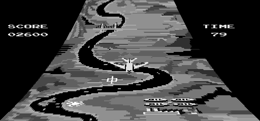
Also, the
use of keystoning to produce an apparent 3D perspective was used at least as far
back as the coin-operated game Skyraider produced by Atari in 1978.
The following Skyraider picture
came from: http://www.arcade-history.com/?n=sky-raider&page=detail&id=2460
The
image being keystoned is a scrolling playfield, not a static image.
Additionally, the only method shown by Dawson '638 to
determine the aircraft's position is to manually move a cursor around a plan
view map. From Column 12, lines 32 - 36:
Freeze frame capability is
supported by the invention. In this mode, the aircraft position is updated using
the cursor. If the aircraft flies off the screen, the display will snap back in
at the appropriate place. This capability is implemented in plan view only.
No method is shown for
determining (or using) the aircraft's orientation.
The final result is
that the Examiner was correct when he stated that he was listing Dawson
5,178,638 (along with other patents) because they were of [only] general
interest.
Dawson does not anticipate '073.
F. European Patent Application EP0399670,
Airborne computer generated
image display systems filed April 27, 1990 by Schofield and O'Leary
(British Aerospace) (EP0399670.pdf)
(Note that British Aerospace merged with Marconi Electronic
Systems in November 1999 and is now called BAE Systems. http://www.graduates-baesystems.com/html/corporateTimeline.php)
The EPO application was
abandoned in 1995. (See EP1.pdf)
This application claims priority from UK application
GB19890012026 dated May 5, 1989. However, no UK patent seems to have been
issued.
The states designated
by the European application were Germany, France, Great Britain, Italy,
Netherlands, and Sweden.
The
status of the application in the Canadian Patent Office shows that an
application was also filed in Japan. (See CA2016359)
There is no evidence yet that any
patent resulting from these applications was issued anywhere. Normally that
would be irrelevant but the fact that no patents were issued suggests that the
Examiners in the various countries did not find anything novel or unobvious in
the applications, and that may aid in interpreting the application.
The earliest date is of the UK
application (GB19890012026 dated May 5, 1989) so the terms in EP0399670
will be given the meanings they would have had to a Person Having
Ordinary Skill in the Art (POSITA) circa 1989.
Let's get started.
Schofield describes the state of the art of Airborne
computer generated image (ACGI) systems circa 1989 in Column 1 line 36 through
Column 2 line 3:
Airborne computer generated image (ACGI) systems have been
proposed which generate perspective terrain views of the outside world from a
combination of pre-stored geographical data and from signals provided by the
aircraft navigational system e.g .the inertial navigation system (INS).
Such ACGI systems
essentially complement the pilot's view from the cockpit or during periods of
poor visibility complement displays produced by aircraft sensors such as video
cameras, infra-red detectors or radar. ACGI systems are intended to
reduce the pilot's overall visual task load. However, hitherto no pilot, other
than one in training on a ground based aircraft simulator, has been required to
fly a complete all-weather mission from take-off to landing relying solely on a
real-time computer generated image of the outside world displayed to him within
the cockpit by such an ACGI system. Moreover, until recently the full
operational potential offered by the introduction of such ACGI systems was
hampered by the lack of suitable high speed digital processors and high capacity
mass storage media.
Emphasis added.
Thus, Airborne computer generated
image (ACGI) systems are already known which combine pre-stored geographical
data with video cameras, infra-red detectors, or radar to produce
"perspective terrain views"
Schofield describes what is
already known in Column 6, line 17 through Column 7 line 34:
In
Figure 1 an ACGI system comprises a terrain data base 1 containing pre-stored
land-mass geographical data relating to features such as rivers, mountains
valleys, roads, coastlines. The data base contains type, positional, height,
colour and other data relating to these features for all points spaced every few
metres all over the world, or at least over that portions of the world over
which the aircraft will operate.
The terrain data base is divided into ground and culture
data bases. The ground data base consists of a network of 50m sided rectangles
with a spot height given for every intersection with colour information. The
culture data base includes: 2D features such as roads and railways, with the end
points and colour being stored for each rectangle; 3-d symbology for pylons,
spires, chimneys with positional data symbol type and colour; block culture
represented by polyhedra for example for urban areas and for forests. In
addition to the terrain data base there may be provided a tactical data base for
flight path and weapon site information, and a dynamic data base for the
collection of new information on targets and threats gathered by the aircraft
sensors during a mission. For clarity these are shown here.
Appropriate extracts from the terrain data base are fed. to
an outside world data base (OSWDB) 2 under the control of a terrain data base
manager (TDBM) system 3. The TDBM has inputs connected to receive navigational
information from the infra-red Linescan system (IRLS) 4 via the SMAC 5, the
global position system (GPS) 6 and inertial navigation (IN) system 7 via a
Kalman Filter 8, and the radar altimeter 9 to ensure that the OSWDB remains
centred on the aircraft's current position and heading.
The
OSWDB produces frames of video information to drive a display, which may be an
LCD,EL a gas plasma area display surrounding the pilot in the cockpit as
described earlier. Preferably it is a full colour, high resolution LCD.
So far what has been described is a known ACGI system which
in the past would have been used as a separate system to complement the view
ahead as displayed by an aircraft sensor system such as a low light television
system. The pilot would only have viewed the ACGI display when the image
produced by the aircraft sensor or his own view through the cockpit was poor due
to low light or bad weather. Figure 1 shows how that known system has been
adapted so that the ACGI is the prime display system used by the pilot enhanced
where necessary by information from aircraft sensors.
The adaptation comprises a video comparator circuit 11
connected to receive and compare the ACGI image with an image produced by one or
more aircraft sensors. In the system shown the aircraft sensors used are,
forward looking infra-red (FLIR) 12 infra-red search and track (IRST) 13, charge
coupled device (CCd) 14, radar 15, obstruction warning device 16, millimetric
radar (MMW) 17, Laser Ranger and Marked Target Seeker (LRMTS) 18, Radar Warning
Receiver, Radar Homing and Warning Receiver (RWR/RHWR) 19, Missile Approach
Warner and Missile Launch Warner (MAW/MLW) 20, joint tactical information
distribution system (JTIDS) 21, Portable Data Store (PODS) 22 and sideways
looking airborne radar (SLAR) 23. The outputs of all these sensors are fed to a
data fusion microprocessor 24 which analyses the video signals produced by each
and selects the average, best or majority video signal and produces a correlated
video signal output to the comparator 11.
Emphasis has been added to show that:
1. The
terrain data base is divided into ground and culture data bases. The ground data
base consists of a network of 50m sided rectangles with a spot height given for
every intersection with colour information. The culture data base includes: 2D
features such as roads and railways, with the end points and colour being stored
for each rectangle; 3-d symbology for pylons, spires, chimneys with positional
data symbol type and colour; block culture represented by polyhedra for example
for urban areas and for forests.
[This will be important later on.]
2. So far what has been described is a known ACGI
system which in the past would have been used as a separate system to complement
the view ahead as displayed by an aircraft sensor system such as a low light
television system.
3. Schofield's
improvement ("adaptation") is to fuse the ACGI image with an image produced by
one or more aircraft sensors (video cameras, infrared cameras, microwave radar,
laser radar, etc.)
Some good examples of ACGI systems that were known circa
1989 are: Beckwith '157 (issued April 21, 1987),
Beckwith '160 (issued July 21, 1987) and Dawson '638 (issued January 12,
1993). As has been shown, none of them anticipate '073.
Schofield describes three
different architectures for his invention.
Architecture 1
From Column 4 line 56 through
Column 5 line 7:
1
Pooled mission processor architecture using a high speed bus, a number of
uncommitted signal processors and mass memories. At start up each processor is
allocated initial functional duties while the mass memories are filled with
appropriate data such as the land mass database. As the mission proceeds the
processors share tasks to even out work load and processor failures may be
accommodated by re allocating tasks according to redundancy algorithms.
Today it would be called a "distributed computing system."
It comes under the category of, "Put in a bunch of processors and let the
Programmer figure out the details to make it work."
Architecture 2
From Column 5 lines 8 - 24:
2
Conventional serial architecture, comprising in series: a land-mass database; a
land-mass data extractor to pull out a selection of the data base canted on the
aircraft's current position; a transformation unit for transforming the
aircraft's current position to world co-ordinates; a point-to-point pixel
unit for producing digital pixel signals for every point on one "frame" of the
scene to be viewed; a frame buffer for storing a complete frame of
digital pixel signals; a video controller for taking digital pixel data from the
frame buffer and passing it to the screen of the display as an analogue video
signal; and, a flat panel display as described above. In an adaptation according
to the invention the video controller may also be fed with overlay signals from
the comparator means or from the look-up table library of control signals and
features.
Emphasis added. The point-to-point pixel unit is an
important clue.
Architecture 3
From Column 5 lines 25 - 40:
3
Multiple Pipeline Architecture, which is a logical extension of the serial
system described above but using parallel data extraction from the land mass
data base on say ten separate lines each associated with its own image store
each looking after a particular small area of the screen. A depth buffer may be
used to remove "hidden" surfaces from the display.In an adaptation according to
the invention the video controllers of each small area of the screen would
receive correspondingly selected signals from the comparator means or form the
new features library or separate comparators may be provided for each line of
the multiple pipe line for comparison with corresponding selected signals from
the sensor data fusion means.
It
like Architecture 2 but does more things in parallel.
Let's focus on Architecture 2
because it is described with the most detail.
From Column 8 lines 26 - 37:
A
land mass or terrain data base 1 as before holds all land profile data in the
operational area of interest in the form of spot heights at regular intervals,
say every 50m. The actual working piece of land area is extracted from the
overall data base 1 by means of a data extraction unit 204. The extract
comprises a fast access memory from which the remainder of the system can work
very quickly. As the aircraft moves in air space the small area extracted by the
unit 204 is updated from the main data base 1 to keep the aircraft at the centre
of the extract.
The terrain data base contains digital elevation data for a
50m grid. However, it contains more than just digital elevation data. As
previously noted from Column 6 lines 26 - 36:
The
terrain data base is divided into ground and culture data bases. The ground data
base consists of a network of 50m sided rectangles with a spot height given for
every intersection with colour information. 2D features such as
roads and railways, with the end points and colour being stored for each
rectangle; 3-d symbology for pylons, spires, chimneys with positional
data symbol type and colour; The culture data base includes:block culture
represented by polyhedra for example for urban areas and for forests.
Emphasis added.
Continuing from Column 8 lines 38 - 49:
The
transformation processor unit 200 receives world co-ordinates and the aircraft's
attitude in 3-D air space and transforms the display area from the extract held
in the unit 204 into co-ordinates which are converted to a 3-D perspective view
of the land-mass in the vicinity of the aircraft.
The
point-to-pixel processor 201 takes data points operated on by the transformation
processor 200 and converts them to points on the flat display in say 512 x 512
pixel format. This process will include filling, shading and symbol overlay
routines well known to those skilled in the art.
The
point-to-pixel processor 201 takes data points operated on by the transformation
processor 200 and converts them to points on the flat display in say 512 x 512
pixel format.
So far, all we
have is a system that transforms points and converts them to points on the
display.
But we also
have: This process will include filling, shading and symbol overlay routines well
known to those skilled in the art.
The big question is, "What is being filled and shaded?"
Remember that
the terrain data base is divided into ground and culture data bases. The
ground database contains points and the culture data base contains
"2D features such as roads and railways, with the end points
and colour being stored for each rectangle."
Are the Digital Elevation points being converted into
polygons and are those the entities being filled and shaded? Or is it the 2D
features in the cultural database that are filled?
Based on the ACGI systems known at or around the time the
Schofield invention was made (Beckwith and Dawson) it is reasonable to assume
that since Schofield's terrain database contains both digital elevation points
(as points) and cultural data (in the form of 2D features such as roads and
railways), the digital elevation points are being transformed and
displayed as points and it is the cultural data that undergoes filling and
shading.
Finally, there is the definition
of "perspective." Does Schofield present the user with true 3D projected image
data? Perhaps he uses the method taught by Dawson '220 which uses keystoning
(squeezing the image into a trapezoidal shape).
The only clue is where Schofield describes one of his
preferred architectures. From Column 5, lines 8 - 24:
2
Conventional serial architecture, comprising in series: a land-mass database;
a land-mass data
extractor to pull out a selection of the data base canted on the aircraft's
current position; a transformation unit for transforming the aircraft's
current position to world co-ordinates; a point-to-point pixel unit for
producing digital pixel signals for every point on one "frame" of the scene to
be viewed; a frame buffer for storing a complete frame of digital pixel signals;
a video controller for taking digital pixel data from the frame buffer and
passing it to the screen of the display as an analogue video signal; and, a flat
panel display as described above. In an adaptation according to the invention
the video controller may also be fed with overlay signals from the comparator
means or from the look-up table library of control signals and features.
The word "canted" means "tilted" or "sloped" which suggests
Dawson's keystoning method.
From the American Heritage Dictionary entry at http://dictionary.reference.com/browse/canted
v. cant·ed, cant·ing, cants
v. tr.
1.
To set at an oblique angle; tilt.
2. To give a slanting edge to; bevel.
3. To change the direction of
suddenly.
v. intr.
1. To lean to one side; slant.
2. To take an oblique direction or
course; swing around, as a ship.
[Middle English, side, from Old
North French, from Vulgar Latin *cantus, corner, from Latin canthus, rim of wheel,
tire, of Celtic origin.]
It is unlikely that "canted"
meant something different in 1989.
For at least the reasons discussed
above, EP0399670 does not anticipate '073.
Jed Margolin
November 26, 2007
Minor
Revision/Format: August 22, 2008
.end

 (kant) Pronunciation Key