Schematics For Hard Drivin'/Race Drivin' ADSP, Motor Amplifier, and DSK Boards
This page mentions several people who worked on Hard Drivin'/Race Drivin' so I want to mention the entire team: Rick Moncrief (Project Leader), Max Behensky (Programmer), Stephanie Mott (Programmer), Jed Margolin (Engineer), and Erik Durfey (Technician). You can read more about us on the Hard Drivin'/Race Drivin' Credit Screen. Just press the Abort switch while the game is in Attract Mode and the Credit Screen will immediately appear. We also listed all the other people at Atari Games who helped us, which was about half the company.
Because the schematics for several of the boards used in Hard Drivin'/Race Drivin' were not published in the game manuals I am posting them here.
The original schematics were B Size (11"x17") so I am posting each one as two 8.5"x11" sheets. The left side of the sheet is first, followed by the right side.
I regret that I am not able to provide very much in the way of support for people wanting to troubleshoot their boards.
Jed Margolin
March 9, 2002 Revised: 3/18/2002,
5/10/2002, 7/18/2002, 4/14/2004, 8/26/2004, 4/27/2009, 1/16/2010, 10/30/2010, 5/1/2019
October 31, 2023 - A Race Drivin’ fan has put the schematics back together into their original 11” x 17” format. Thank you, James.
The Hard Driving/Race Drivin’ Main Board was already in 11” x 17” format. HD_Main
James has also made a document explaining how to connect the Game Link. Game Link.
Make sure to use a Null Modem Serial cable.
I haven’t verified the instructions because I don’t have two Race Drivin’ games. I don’t even have one anymore. It went to Strong Museum of Play in Rochester, New York. https://www.museumofplay.org/
If you are surprised that I am still alive after all this time, so am I.
Jed
Index
Main Board GSP
The circuit for the Main Board GSP system was not included as part of the published schematic package in an attempt to keep some of the details secret.
Hard Drivin' used a 68010 main processor, a Texas Instruments TMS34010 Graphics Signal Processor for the graphics engine, an Analog Devices ADSP-2100 DSP for graphics math, and another TMS34010 solely to do the calculations for the car model.
When used as TI intended, the TMS34010 used for the graphics engine would not have been fast enough for the game. It had a 16-bit memory data bus, so the number of pixels you could fill in one memory operation depended on how many bits per pixel you used. If you had 4 bits per pixel you could fill a maximum of 4 pixels per memory operation. Four bits per pixel were not enough. And even then it was too slow.
To speed things up I took advantage of memory granularity. VRAMs were originally 64K x 1. Then they were 64K x 4. Those were the ones I used. In order to have enough memory for screen buffers that were 512 x 384 x 8 bits I needed 32 VRAMs. (The TMS34010 also used the VRAM memory for its program.)
So I paired them up as 16 banks of 64Kx8 (32 64Kx4 VRAMs).
By telling the TMS34010 that there was only one bit per pixel it could select 16 pixels per memory operation. In this mode, the actual color came from an 8-bit color register.
That required one memory organization.
However, making the pixels come out in the right order when shifted out of the VRAM shift registers required a different organization.
In addition, since the TMS34010 also used the VRAM for program storage, it required yet another memory organization.
Fortunately, the TMS34010 had a huge memory space, so I switched the memory organization according to the memory space used.
Programs used one memory space, polygon creation used another, and Graphic Display used a third. The memory organization was changed dynamically according to the address being selected. (I guess you would call it a dynamic dynamic memory.)
The first prototype used a handful of buffers. Later, Don Paauw put everything in a gate array, along with enough security features to keep the pirates occupied for awhile. The schematic refers to the part as a 34012. I did that so that the pirates would think it was a Texas Instruments part so when they tried to order it and Texas Instruments told them there was no such part, they would think Texas Instruments was lying and would waste time trying to find out what was going on.
Because of the granularity of the VRAMs I
added circuitry to allow single-pixel scrolling.
The GSP system in the MultiSync Main Board
used a memory organization of only 8 banks of 64Kx8 (16 64Kx4 VRAMs) in order
to save money. In addition to having less memory, the system could only fill 8
pixels at at time instead of 16.
For some reason the second TMS34010 (the MSP) was also left out of the Hard Drivin' schematic. However, it was shown on the Steel Talons schematic.
MSP stands for Model Signal Processor to distinguish it from the first TMS34010, the Graphics Signal Processor. The reason Hard Drivin' drives so much like a real car is that it models the physics of how cars work and interact with their environment. The TMS34010 is actually a 32-bit processor with extra instructions for doing graphics and has a nice interface for connecting to a host processor. It also had a C Compiler.
You may have noticed that the Credit Screen lists Doug Milliken as a Test Driver. He is listed as a Test Driver because Atari didn't want anyone to know what he really did.
When we started Hard Drivin' we wanted it to be as accurate as possible. That meant doing an accurate car model to mathematically describe the physics of how the parts of the car (engine, transmission, springs, shock absorbers, tires, etc.) react to each other, to the road, and to the driver's inputs.
It also describes how the forces are transmitted back to the driver through the force-feedback steering wheel.
The pioneer in the field (in the 1950s) was William Milliken of Milliken Research. He son, Doug, has continued his father's work. Doug is probably the world's leading expert in car modeling. Doug and his father wrote the book on car modeling. And I mean that literally. (Go to Amazon.com and check out "Race Car Vehicle Dynamics (R146)" by William F. Milliken, Douglas L. Milliken).
Doug is also a good friend of Max's.
We hired Doug as a consultant to develop the car model. At the time (1980s) most of the work in car modeling was done to look at how the different parts of the car worked together within certain narrow speed ranges.
Our car had to work at all speeds. The way the car works at high speed is different than at slow speeds, such as when you are stopped and just starting to roll.
Doug and Max worked together to develop a car model that smoothly and dynamically changes depending on the mode. (Doug and Max are the smartest people I know.)
Atari had us list Doug as a Test Driver because they didn't want anyone to know we were doing real car modeling.
The modeling is so good (along with the moving dashboard contributed by Erik Durfey) that some people swear the game has a powered moving seat.
BTW, the seat position sensor scales the
force feedback in the steering wheel. Presumably, a young person will have the
seat forward and will get less force, and an adult will have it further back
and get more force.
The TMS34010 does not have floating point, so Max could only model the car as having two wheels.
For Race Drivin' I put an AT&T DSP32C on the DSK Board (DSK stands for Driver Speed Kit.) The DSP32C is faster than the TMS34010 and has floating point. Because Max wrote the Car Model in C he was able to port it to the DSP32C in an afternoon. After that, he was able to have it execute a car model with four wheels. It also has a faster update rate.
The difference is very apparent when you
drive the Original Track in Race Drivin'.
The ADSP Board uses an Analog Devices ADSP-2100 in a Pin-Grid Array (PGA) package.
The ADSP II Board is identical to the ADSP Board except it uses the ADSP-2100 in the Plastic-Quad-Flat-Pack (PQFP) package.
ADSP and ADSP II Boards
are electrically and mechanically equivalent.
The DSK (Driver Speed Kit) Board was used in Race Drivin' only. It contains an AT&T DSP32C Floating Point DSP (ASIC61) to provide for a better car model, as well as extra RAM and ROM, and a Texas Instruments TMS320P15 single-chip DSP (ASIC65) for extra security. Atari called the DSP32C and TMS320P15 ASICxx (or in some places (PLDxx) to disguise the fact that they were commercially available ICs. I doubt it fooled anyone.
The DSP32C was originally made by AT&T for their in-house use. Then they started selling it outside the company. Then they spun off their semiconductor business into Lucent Technologies. Then Lucent spun off semiconductors into a company called Agere. Unfortunately, the DSP32C seems to have been discontinued. The DSP32C documentation is a series of manuals about a foot wide. However, I have posted the basic hardware datasheet here (DSP32C 2.9 MBytes PDF).
The TMS320P15 was (is?) a single-chip version of the TMS32010, the first successful DSP. It had internal EPROM protected by a security bit. Once the security bit was programmed you were not supposed to be able to dump the contents of the EPROM. In the part with a window you could only erase the Security Bit by erasing the EPROM program. We used the part without a window so it could not be erased. (The OTP version was also lots cheaper.)
If you ground pin 4 on the TMS320P15 (signal 'P2') and then reset the chip (turning the game off for a few seconds and then turning it on again will do the trick) the TMS320P15 will send the Atari Games copyright message in Morse code which can be received on a standard AM radio by holding it near the DSK Board. Tune around the AM band to get the best quality signal.
I added this to my Self-Test code so that in the event Race Drivin' was pirated I would be able to tell if the program in the TMS320P15 had been reverse engineered or if the chip's security feature had been hacked. (The Morse code program is not accessible from the game code.)
As far as I know, Race Drivin' was never pirated, although Hard Drivin' was.
The TMS320P15 was used in
another game (Road Riot) that was pirated. When I checked for the Morse
code program in the pirated game, it was played loud and clear. So much for
Texas Instrument's claim that the chip's security was actually worth a damn.
After several months looking for a real copy of the Motor Amp, I finally found it! This is the Motor Amp used in the Cockpit versions of Hard Drivin' and Race Drivin'.
The Steering Assembly Troubleshooting Guide in the Hard Drivin' and Race Drivin' game manuals helps you narrow down problems to either the Motor or the Motor Amp and then instructs you to contact Atari Customer Service. That is no longer an option since Atari Games no longer exists except as a game development group for home games. It isn't even called Atari Games; it's called Midway Games West.
First a warning.
The voltages used in the Motor and in the Motor Amp are hazardous. Unless you are experienced working with High Voltages, Don't Try to Fix it Yourself. (You really can kill yourself.) In addition, parts of the Motor Amp are NOT isolated from the power line. Working on these parts of the Motor Amp (especially using line-powered equipment like an oscilloscope) requires the use of an isolation transformer. Because the Motor can draw a Lot of current, the isolation transformer has to be a Big Mother. (Variacs are generally Not isolated.) It's not worth getting injured or killed over a video game.
The Motor Amp is interfaced to the game board through the use of opto-isolators in the digital lines. The Motor Amp board was designed to meet U.L. safety standards for high voltage products.
Start by checking the usual suspects (blown fuses, charred components, the smell of smoke, etc.) as well as whether the Force-Feedback has been turned off in the Disable Broken Controls screen in the Test Menu.
The next thing is to determine if the problem is with the Motor, the Motor Amp, the Motor Position Pot, or the A/Ds.
There is a screen in the Test Menu (Special Functions > Main Board Controls > Steering Wheel) that allows you to select various Motor tests that operate open-loop and do not use the position pot.
If these tests work, you know the problem is not with the Motor or the Motor Amp.
There are other screens to read the pots. The Motor position is read by both the 12-bit A/D and the 8-bit A/D. Both must be working or the program knows there is a problem and turns off the Force-Feedback Steering.
There is also an Operator option to turn off Force-Feedback Steering in Disable Broken Controls.
If the Steering Wheel Tests don't move the Motor, the problem is either with the Motor or the Motor Amp.
1. Make sure the ribbon cable is plugged in correctly with Pin 1 of J15 on the Main Board going to Pin 1 of J6 on the Motor Amp Board.
2. There are jumpers on the Motor Amp Board in case we wanted to operate more than one Motor Amp (I don't think we ever did.) In order for it to work in the game, the jumper must be installed in E1 (the one closest to the connector).
3. A voltmeter across the Motor should tell you if the Motor Amp is producing drive for the Motor. (The Send-Force Tests can be used to output a steady drive.)
4. A good way to test the Motor is to connect a DC voltage across it. (Disconnect it from the Motor Amp first.) I believe the motor is either a 60VDC or a 90VDC motor. However, since 60VDC (or 90VDC) produces full torque. I would guess something lower would work. A 24VAC transformer, when half-wave or full-wave rectified and filtered, will produce about 36VDC. That should be enough to test the Motor. (I would guess a 1000 uF filter capacitor would be sufficient.)
Note that if you rectify and filter the 120VAC line you will get about 160 VDC. That is *way* too much for the Motor.
The motor is a DC motor that uses brushes. When it stops working it is usually because the brushes are either worn out or just plain dirty.
I have brought some brush motors back to life by spraying Contact Cleaner at the commutator and brushes. (These were not Hard Drivin' motors.)
I have taken other brush motors apart (also not Hard Drivin' motors), carefully cleaned the brushes and the commutator, and put everything back. Warning, the brushes in a motor are usually spring-loaded.
I don't know how easily this particular motor comes apart.
There isn't much else to go wrong with a DC motor.
If the brushes are worn out you should be able to buy new ones. I have never had to, so I don't know how that works.
You may be able to find someone in your area who rebuilds electric motors. (Or maybe I'm just dating myself.)
If I had to buy a new Motor, I would figure out exactly who made it and what size it is, and look for it online at places like McMaster-Carr. The last time I tried www.mcmaster.com they were still there.
Sorry, I don't have any extra Motors, just the one in my own game.
5. If the Motor is ok, the next thing to look at is the Motor Amp.
The Motor Amp can be tested without the Motor by connecting a small 120VAC light bulb to the output (25 Watt - 40 Watt) and by jumpering the Thermal Protector. I suggest making your own cable to plug into J2 on the Motor Amp Board. (The wiring diagram in the manual shows it as P222.) Pins 1 and 4 normally go to the Thermal Protector in the Motor. (The Thermal Protector opens up if the Motor overheats.) Therefore, P2 Pins 1 and 4 must be jumpered for the Light Bulb tester.
If all you are going to do is plug in the Light Bulb Tester and look for it to light up during the Send Force Tests, then that's fine.
If you are going to troubleshoot the Motor Amp, You Need An Isolation Transformer.
If you don't have an
isolation transformer, you can make your own by connecting two 24VAC 3Amp
transformers back-to-back. This only works if you are using a light bulb as a
load. The Motor draws too much current for this kludge.
At this point you are on
your own. Sorry. (I didn't design the Motor circuit. I just gave Rick the
interface he asked for, and I also wrote the test software for it.)
[Information on jumpering the Motor Thermal Protector, the ribbon cable orientation, and the Motor Amp Board jumpers provided by Tony Rossi. Thank you, Tony.]
In April 2009 I received an email from Mike Grzehowiak with very good information about the motor. (Thank you, Mike.)
Subject: Motor brushes source
Message:
1st, thanks for all the information supplied on this website. I'm sure it will be helpful at a time in the future when the machine decides to act up again. (Monitor just went out yesterday but I did get some racing in before it did that).
I had to replace the motor brushes just recently, so wanted to pass on the info if you wanted to add it on your site.
Ohio Electric Motors, Inc.
828-626-2901 Ext 235
fax 828-626-2155
are the original manufacturers of the motor and as of 4-2009 had a few brushes in stock (part# B-250407-02 at $18.60 each brush, plus a $100 minimum order).
I was able to locate them from another source at a reasonable price. They are:
Ohio Carbon Industries
705 US Hwy 224
Nova, OH 44859
Phone: (419) 736-3010
Toll free: (888) 248-5029
Fax: (419) 736-3011
www.ohiocarbon.com
Part number is 2220282 at $8.50 each. ($15 minimum order).
Hope this helps. I also have a pic of the replacement brushes, but they fit
just fine.
Thanks,
Mike
Hard Drivin' and Race Drivin' used the same Sound Board. I don't remember if Race Drivin' added more ROMS to the board.
The complete set of Hard Drivin' schematics that came in the game manual used to be available at www.spies.com/arcade/schematics/ . They seem to have disappeared.
I have found another set at http://www.cityofberwyn.com/schematics/index.htm
There are several manuals available at:
http://tamdb.net/index.php?page=Manuals&PHPSESSID=0f35d13e3363213cf728ebd7edf3d459&lettre=H
Here is a mirrored copy of the Hard Drivin' Manual
TM-327 3rd printing (13MB).
And here is a mirrored copy of the Hard Drivin' Compact Manual TM-329 2nd printing
(5MB).
Thanks to the generosity of Bob Langelius I now have a new seat for my Race Drivin' . (One day the bottom of the old seat shattered.)
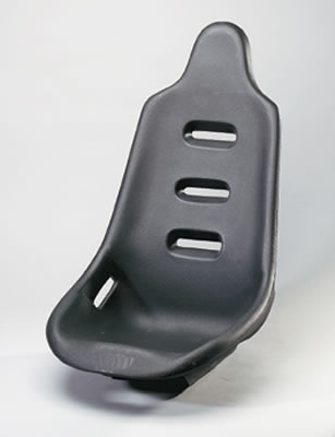 The new seat is from Summit Racing Equipment at www.SummitRacing.com . Warning, their
Web site needs some work. The printed catalog is much easier to use.
The new seat is from Summit Racing Equipment at www.SummitRacing.com . Warning, their
Web site needs some work. The printed catalog is much easier to use.
The catalog number of the seat is SUM-G1100
. Mine is black; they are also available in red, yellow, and blue. They also
have some snazzy looking seat covers for them.
The holes in my new seat do not match the holes in my old seat. I will describe what I did; you may be able to come up with a better method for installing the new seat. (Bear in mind that my game was a preproduction prototype; production games might have been done differently.)
1. I got some new bolts because the mounting nuts in the new seat are bigger than the ones in the old seat. The bolts for the new seat are 3/8 x 16 x 3/4" long. (The old ones were 5/16 x 18 x 3/4" .) I also bought new flat washers and tooth washers for the new bolts. (The store was out of split washers.)
2. My original
plan was to drill new holes in the mounting plate. However, the mounting plate
on the seat mechanism is 3/16" steel which is difficult to work using
common tools, so I went with Plan B which was to enlarge one of the center
holes and mount the new seat with just the two center holes. I did this by
drilling an 1/8" hole (with a sharp drill bit) near the hole I wanted to
enlarge and then using a 3/8" drill bit to enlarge it so that it
encroached into the original hole. Then I used a file to smooth out the
resulting elliptical enlarged hole.
 3. In the old seat, the captive mounting nuts appear to be epoxied to
the inside bottom surface of the seat and they extend a small distance beyond
the bottom side. It appears to be designed to use mounting holes that are
large enough to accommodate the nuts and the area immediately around it so that
the remaining surface of the seat is supported by whatever it is mounted on.
Otherwise, the seat and its occupant are supported solely by the mounting nuts
which, under load, could possibly pop out. In any event it would place a great
deal of stress around the nuts instead of it being evenly distributed around
the larger seat surface.
3. In the old seat, the captive mounting nuts appear to be epoxied to
the inside bottom surface of the seat and they extend a small distance beyond
the bottom side. It appears to be designed to use mounting holes that are
large enough to accommodate the nuts and the area immediately around it so that
the remaining surface of the seat is supported by whatever it is mounted on.
Otherwise, the seat and its occupant are supported solely by the mounting nuts
which, under load, could possibly pop out. In any event it would place a great
deal of stress around the nuts instead of it being evenly distributed around
the larger seat surface.
This is probably why my seat was additionally secured by four toggle bolts through holes in the bottom of the seat.
(The seat bottom has two surfaces: the surface you sit on and the surface that is bolted to the mounting plate, with enough room between them to install a toggle bolt. )
Since I cannot see into the new seat I will assume the captive nuts were done in a similar way, as opposed to having the mounting nuts attached to a plate inside the seat. (On the other hand, since the seat is intended to be used in a moving vehicle, perhaps the seat can be mounted solely to the nuts.)
 To avoid having the seat resting on the captive nuts I placed a sheet of
1/8" hard rubber between the seat and the mounting plate. (I would have
used 1/4" hard rubber if I had had it.) As a result, the seat and
occupant are supported by the rubber sheet and not by the mounting nuts.
To avoid having the seat resting on the captive nuts I placed a sheet of
1/8" hard rubber between the seat and the mounting plate. (I would have
used 1/4" hard rubber if I had had it.) As a result, the seat and
occupant are supported by the rubber sheet and not by the mounting nuts.
While this method might not withstand heavy
arcade use and probably wouldn't pass the standard shipping drop test, it's ok
for my use. If I ever need to ship it I will strap the seat down through the
slots conveniently placed in the side of the seat.
Plan C would have been to fabricate some
kind of adapter bracket. However, that would have been a lot of work. Besides,
it would have raised the seat, which I didn't want to do.
EPROMS and GALS - Part Numbers
Race Drivin' Cockpit EPROMs and GALs - Final North American Version (Linked Games)
This is for Version 2.4, the final version.
(Please do not ask me for ROM files.)
All ROMs are 137448-200 (27C512, 200 ns) unless otherwise noted.
==================================================================
Main Board:
Loc. P/N Chksum
ImageFile
Loc. P/N Chksum ImageFile
210R 136077-5001
$5D01 5001.bin 200R
136077-5002 $F402 5002.bin
210S 136077-5003
$5E03 5003.bin 200S
136077-5004 $8704 5004.bin
210T 136077-5005
$9E05 5005.bin 200T
136077-5006 $7906 5006.bin
210U 136077-4007
$5307 4007.bin 200U
136077-4008 $0608 4008.bin
210V 136077-4009
$FA09 4009.bin 200V
136077-4010 $C110 4010.bin
210W 136077-1011
$5111 1011.bin 200W 136077-1012
$C312 1012.bin
210X 136077-1013
$D613 1013.bin 200X
136077-1014 $F214 1014.bin
210Y 136077-4015
$E215 4015.bin 200Y
136077-4016 $3C16 4016.bin
ADSP Board:
Programmed Board
Part Number Checksum
Location ImageFile
136077-1021
$6A21 10H
1021.bin
136077-1022
$CB22 10J
1022.bin
136077-1023
$1A23 10K
1023.bin
136077-1024
$A724 10L
1024.bin
DSK Board: - Use 27C512-150ns
Programmed Board
Part Number Checksum
Location ImageFile
136077-1028
$8028 30F
1028.bin
136077-1029
$8029 10F
1029.bin
136077-4030
$7E30 30E
4030.bin
136077-4031
$1C31 10E
4031.bin
GALs are GAL20V8, 15 ns
Programmed
User
Board
Part Number Checksum
Signature Location
Function File
136077-1025
$5133 077-1025
40B Address Decode dskx1.JED
136077-1026
$50B9 077-1026
60B Address Decode dskx2.JED
Sound Board:
Programmed
Board
Part Number Checksum
Location Version Function ImageFile
136077-1032
$A832 70N (RH)
A Program 1032.bin
136077-1033
$E533 45N (RL)
A Program 1033.bin
Sound Data Memory is 8 bits.
136052-1123
$EE01 65A (8)
A Sound Data 65A.bin
136052-1124
$5F02 55A (8)
A Sound Data 55A.bin
136052-3125
$CC03 45A (8)
C Sound Data 45A.bin
136052-1126
$2B09 30A (8)
A Sound Data 30A.bin
136077-1017 $DB09
45C (8) A Sound Data
45C.bin
I think the order of the Sound Data ROMS doesn't matter. Mine are:
136052-1123
$EE01 65A
136052-1124
$5F02 55A
136052-3125
$CC03 55C (45A)
136052-1126
$2B09 65C (30A)
136077-1017 $DB09
45C
Self-Test may think there are supposed to be 6 ROMS. It is wrong.
GALs are GAL16V8, 25 ns
Programmed
User
Board
Part Number Checksum
Signature Location
Function File
136052-1139
$6739 052-1139 95A
Address Decode sndx1.JED
136052-1140
$59E0 052-1140
95C Address Decode sndx2.JED
Race Drivin' Cockpit EPROMs and GALs - Final UK Version (Right-Hand Drive, Linked Games)
This is for Version 2.4, the final version. Note that there are only two ROMs (210W and 200W) that are different from the North American version.
(Please do not ask me for ROM files.)
All ROMs are 137448-200 (27C512, 200 ns) unless otherwise noted.
==================================================================
Main Board:
Loc. P/N Chksum
ImageFile
Loc. P/N Chksum ImageFile
210R 136077-5001
$5D01 5001.bin 200R
136077-5002 $F402 5002.bin
210S 136077-5003
$5E03 5003.bin 200S
136077-5004 $8704 5004.bin
210T 136077-5005
$9E05 5005.bin 200T
136077-5006 $7906 5006.bin
210U 136077-4007
$5307 4007.bin 200U
136077-4008 $0608 4008.bin
210V 136077-4009
$FA09 4009.bin 200V
136077-4010 $C110 4010.bin
210W 136077-1111 $AC11
1111.bin 200W 136077-1112
$EA12 1112.bin
210X 136077-1013
$D613 1013.bin 200X
136077-1014 $F214 1014.bin
210Y 136077-4015
$E215 4015.bin 200Y
136077-4016 $3C16 4016.bin
ADSP Board: Same as North American
DSK Board: Same as North American
Sound Board: Same as North American
Race Drivin' Cockpit EPROMs and GALs - Final German Version (Left-Hand Drive, Linked Games)
This is for Version G2.4, the final version.
(Please do not ask me for ROM files.)
All ROMs are 137448-200 (27C512, 200 ns) unless otherwise noted.
==================================================================
Main Board:
Loc. P/N Chksum
ImageFile
Loc. P/N Chksum ImageFile
210R 136077-5201 $DC01
5201.bin 200R 136077-5202
$7602 5202.bin
210S 136077-5203
$AB03 5203.bin 200S
136077-5204 $9704 5204.bin
210T 136077-5205
$3F05 5205.bin 200T
136077-5206 $0206 5206.bin
210U 136077-4007
$5307 4007.bin 200U
136077-4008 $0608 4008.bin
210V 136077-4009
$FA09 4009.bin 200V
136077-4010 $C110 4010.bin
210W 136077-1111
$AC11 1111.bin 200W
136077-1112 $EA12 1112.bin
210X 136077-1013
$D613 1013.bin 200X
136077-1014 $F214 1014.bin
210Y 136077-4015
$E215 4015.bin 200Y
136077-4016 $3C16 4016.bin
ADSP Board: Same as North American
DSK Board: Same as North American
Sound Board: Same as North American
Race Drivin' Compact EPROMs - Final North American Version (Linked Games)
This is for Version 1.9, the final version. Uses MultiSync Main Board.
(Please do not ask me for ROM files.)
All ROMs are 137448-200 (27C512, 200 ns) unless otherwise noted.
==================================================================
Main Board:
Loc. P/N Chksum
ImageFile
Loc. P/N Chksum ImageFile
210R 136078-5001
$DE01 U5001.bin 200R
136078-5002 $A002 U5002.bin
210S 136078-5003
$7903 U5003.bin 200S 136078-5004
$A204 U5004.bin
210T 136078-5005
$B705 U5005.bin 200T
136078-5006 $E906 U5006.bin
210U 136078-4007
$1B07 U4007.bin 200U
136078-4008 $7F08 U4008.bin
210V 136078-4009
$B509 U4009.bin 200V
136078-4010 $6A10 U4010.bin
210W 136078-1011
$5111 U1011.bin 200W
136078-1012 $C312 U1012.bin
210X 136078-1013
$D613 U1013.bin 200X
136078-1014 $F214 U1014.bin
210Y 136078-4015
$7815 U4015.bin 200Y
136078-4016 $E416 U4016.bin
DSK Board (-02 version):
Use 27C512-150ns
Programmed Board
Part Number Checksum
Location ImageFile
136077-1027
$0527 30J
1027.bin
136078-1030
$7C30 30E
1030.bin
136078-1031
$1F31 10E
1031.bin
GALs are GAL20V8, 15 ns
Programmed
User
Board
Part Number Checksum
Signature Location
Function File
136077-1025
$5133 077-1025
40B Address Decode dskx1.JED
136077-1026
$50B9 077-1026
60B Address Decode dskx2.JED
Race Drivin' Compact EPROMs - Final UK Version (Right Hand Drive, Linked Games)
This is for Version UK1.9, the final version. Uses MultiSync Main Board. Note that there are only two ROMs (210W and 200W) that are different from the North American version.
(Please do not ask me for ROM files.)
All ROMs are 137448-200 (27C512, 200 ns) unless otherwise noted.
==================================================================
Main Board:
Loc. P/N Chksum
ImageFile
Loc. P/N Chksum ImageFile
210R 136078-5001
$DE01 U5001.bin 200R
136078-5002 $A002 U5002.bin
210S 136078-5003
$7903 U5003.bin 200S
136078-5004 $A204 U5004.bin
210T 136078-5005
$B705 U5005.bin 200T
136078-5006 $E906 U5006.bin
210U 136078-4007
$1B07 U4007.bin 200U
136078-4008 $7F08 U4008.bin
210V 136078-4009
$B509 U4009.bin 200V
136078-4010 $6A10 U4010.bin
210W 136078-1111
$AC11 U1111.bin 200W
136078-1112 $EA12 U1112.bin
210X 136078-1013
$D613 U1013.bin 200X
136078-1014 $F214 U1014.bin
210Y 136078-4015
$7815 U4015.bin 200Y
136078-4016 $E416 U4016.bin
Race Drivin' Compact EPROMs - Final German Version (Left Hand Drive, Linked Games)
This is for Version G1.9, the final version. Uses MultiSync Main Board.
(Please do not ask me for ROM files.)
All ROMs are 137448-200 (27C512, 200 ns) unless otherwise noted.
==================================================================
Main Board:
Loc. P/N Chksum
ImageFile
Loc. P/N Chksum ImageFile
210R 136078-5201
$0401 U5201.bin 200R
136078-5202 $FF02 U5202.bin
210S 136078-5203
$E403 U5203.bin 200S
136078-5204 $B704 U5204.bin
210T 136078-5205
$6A05 U5205.bin 200T
136078-5206 $7F06 U5206.bin
210U 136078-4007
$1B07 U4007.bin 200U
136078-4008 $7F08 U4008.bin
210V 136078-4009
$B509 U4009.bin 200V
136078-4010 $6A10 U4010.bin
210W 136078-1011
$5111 U1011.bin 200W 136078-1012
$C312 U1012.bin
210X 136078-1013
$D613 U1013.bin 200X
136078-1014 $F214 U1014.bin
210Y 136078-4015
$7815 U4015.bin 200Y
136078-4016 $E416 U4016.bin
Hard Drivin'/Race Drivin' ROM Part Number System
Generally, 136052-xxxx was Hard Drivin' Cockpit
136091-xxxx was Hard Drivin' Compact
136088-xxxx was Panorama
136077-xxxx was Race Drivin' Cockpit
136078-xxxx was Race Drivin' Compact
Using Hard Drivin' Cockpit as an example:
136052-nxxx where 'n' was the version number
For example:
136052-0xxx was a pre-production prototype
136052-1xxx was the
first released version. This number increased every
time a new version was released.
136052-xxnn where 'nn'
was which ROM it was in the game. (If there had been more than 99 Programmed
parts in the game we would have had a problem.)
136052-xnxx where n was the World Version Number. For example, 136052-x0xx was the North American Version.
There were four versions that I know about.
Hard Drivin' Cockpit:
North American - 136052-x0xx Left Hand Drive, English
UK
- 136052-x1xx Right Hand Drive,
English
German
- 136052-x2xx LH Drive, German
(Game and Self-Test)
Japanese
- 136052-x?xx Right Hand Drive,
Japanese (Game), English (Self Test)
Hard Drivin' Compact:
North American - 136091-x0xx Left Hand Drive, English
UK
- 136091-x1xx Right Hand Drive,
English
German
- 136091-x2xx Left Hand Drive,
German (Game and Self-Test)
Japanese
- 136091-x?xx Right Hand Drive,
Japanese (Game), English (Self Test)
Race Drivin' Cockpit:
North American - 136077-x0xx Left Hand Drive, English
UK
- 136077-x1xx Right Hand Drive,
English
German
- 136077-x2xx Left Hand Drive,
German (Game and Self-Test)
Japanese
- 136077-x?xx Right Hand Drive,
Japanese (Game), English (Self Test)
Race Drivin' Compact:
North American - 136078-x0xx Left Hand Drive, English
UK
- 136078-x1xx Right Hand Drive,
English
German
- 136078-x2xx Left Hand Drive,
German (Game and Self-Test)
Japanese
- 136078-x?xx Right Hand Drive,
Japanese (Game), English (Self Test)
However, some ROMS were reused and given new part numbers to match the game.
Examples:
Main Board
Race Drivin' Cockpit and Race Drivin' Compact share the following ROMs:
136077-1011 = 136078-1011
136077-1012 = 136078-1012
136077-1013 = 136078-1013
136077-1014 = 136078-1014
Sound Board
All the ROMs on the Race Drivin' Compact
Sound Board are identical to the Sound Board ROMs on Race Drivin' Cockpit. The
final version should be backwards compatible with all previous versions.
DSK Board
The Cockpit ROMs 136077-4030 and 136077-4031 do not match the 136078-1030 and 136078-1031.
On Race Drivin' Cockpit the ROMs 136077-1028 and 136077-1029 contain encrypted data for a security program that was not used. The ROMs were inadvertantly left on the parts list so the game was built and shipped with them. The ROMs do not appear to be on the Compact Version.
A similar thing happened with the ZeroPower
RAMs on the DSK Board. They were intended to save the challenge races of the
winning players but we ran out of time so it was not implemented.
I have made some videos of my Race Drivin'.
It wasn't easy. My first attempt was to mount the camera on a bar that I
clamped across the cockpit struts. The field of view was too small and cut off
part of the picture.
I don't have a spare monitor, and removing the monitor from the cockpit was
more than I was willing to do.
I made an adapter to connect the game to a computer LCD VGA monitor, hoping
that the LCD monitor could handle the game's sync (25 KHz Horizontal, 60 Hz
Vertical). It refused to sync up. I tried several monitors. No Joy.
My last hope was a 19" Vizio LCD TV with a VGA input. Since the TV can
handle 15.734 KHz for analog NTSC and a much higher frequency for VGA, maybe it
would handle the 25KHz from the monitor.
It worked!
The adapter is a VGA connector with resistor pads to reduce the signals from
the game to VGA levels.
After adjusting the TV for picture size and aspect the resulting picture is
better than with the game monitor.
I converted the files from the Flip Camera AVI to WMV (losing picture quality
but reducing file size). Depending on your browser you may need to
right-click and select the appropriate option to save the file, and
then play it. Besides, sometimes you get a better result if you download
the file and then play it.
rd1990_track1.wmv
(17 MBytes)
rd1990_track1_house.wmv
(6 MBytes)
rd1990_track2.wmv
(7 MBytes)
1990_track3.wmv
(20 MBytes)
Video Adapters for Hard Drivin’/Race Drivin’ Cockpit
Horizontal Sync for the Cockpit (Main Board) is 25 KHz, Vertical Sync is 60 Hz. NTSC Horizontal Sync is 15.734 KHz and Vertical Sync is 59.94 Hz. The slowest VGA Mode is 31.778 KHz Horizontal and 60 Hz Vertical (for 640 x 480 x 16 colors) and 31.778 KHz Horizontal and 70 Hz Vertical (for 640 x 480 x 256 colors). I hoped that a TV with a VGA input would be able to sync to a horizontal signal between 15.734 KHz (NTSC) and 31.778 KHz (VGA).
My Vizio VA19L worked! Other TVs didn’t.
Computer Monitors only have to work down to 31.778 KHz. So far I have only found one that would sync to 25 KHz.
The adapter I made to make the videos was on a perf board.
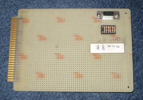
In the Winter of 2018 I decided to make a PC Board for it. I was designing PC Boards for several other projects and having them fabricated in China. The boards were excellent and the cost was very low. For $5 you get 10 PC Boards as long as they are no larger than 100mm x 100mm (3.9” x 3.9”). Shipping costs more than the boards but by ordering several project boards at the same time and combining shipping it costs only the incremental shipping costs.
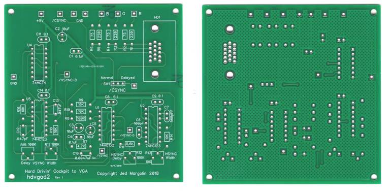
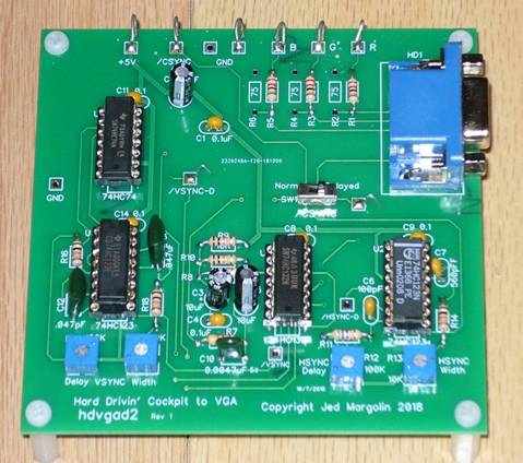
For my first VGA board I spent some time to get the pinouts of the VGA connector right. I got them wrong anyway. Here is Rev 2.
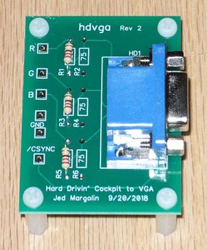
It worked great on my old Vizio VA19L.
Then I tried it on a Samsung T22C350ND. It synced up ok but the horizontal centering did not have enough range. I designed a circuit to delay the horizontal sync so I could center the picture. I made a PC Board for that too.
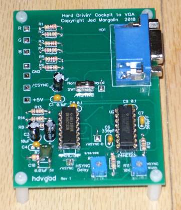
Then I realized that the vertical centering also needed help. More circuitry and another PC Board.

It worked great with my Samsung T22C350ND and really great on my Magnavox 40” LED 40ME324V/F7. Imagine Hard Drivin’/Race Drivin’ on a 40” display. Of course it won’t be HD but if you use an HD camcorder your videos should be better than the ones I made with my Flip Camera.
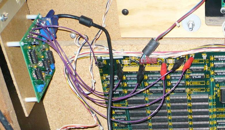
The adapter requires +5V but the test blades along the top on the Main Board provide +5V, GND, R, G, B, /CSYNC. The test blades are not Fastons. I connect to them with alligator clips.
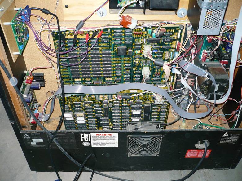
To mount the VGA board I attached a short 1 x 2 to the side of the cabinet with white glue. I also used two screws that were short enough so they didn’t poke through the side. The screws probably aren’t necessary. The VGA board is attached to a piece of tempered hardboard (Masonite). The tempered hardboard is attached to the 1 x 2 with two #6-32 x 1" hanger bolts so I could easily remove the VGA board for shipping. A hanger bolt is a screw where half of it is a wood screw and the other half is a machine screw.
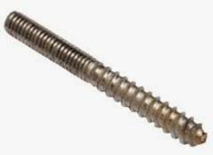
They make a tool to install it but I just used a 6/32 threaded metal standoff with a nut in front of it to keep it from turning as I used a nut driver on the standoff to screw it into the wood.
I got my hanger bolts at Bolt Depot www.boltdepot.com). I got product 13582 Hanger bolts, Steel plain finish, #6-32 x 1" . For a bag of 100 (with shipping) I paid $10.67 . Hanger bolts are such useful devices that I expect to use them again somewhere.
I am posting the Gerber files for the boards so you can order the boards from the fabricator of your choice. I am also posting the design files. I designed the boards using DipTrace. https://diptrace.com/download/download-diptrace/ . The freeware program is limited to 300 pins but is otherwise a fully functional program. If you are already a Maker you will know what to do with the files. If you are not already a Maker (and you want to be) I suggest you read the tutorial I wrote on Making Things.
Project 1 - Simple VGA Adapter - No Delay
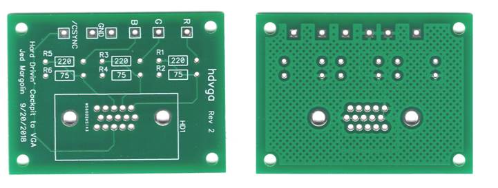

proj1_jm_hdvga-R2.zip contains:
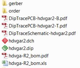
The zip file for ordering the board is in the folder: order > jm_hdvgar2.zip . The board dimensions are: 43.2mm x 58.5mm.
You can examine the board files with the program GerberLogix. The program runs in place, meaning that it does not install anything on your computer. You just run the program. The program is free. And it is here: https://www.easylogix.de/products_detail.php?prog_id=1
Project 2 - VGA Adapter - Adjustable Horizontal and Vertical Delays For Centering
proj2_jm_hdvgad2-R1.zip contains:
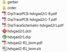
Note: There is a typo. C12 should be 0.047uF. Not pF.
The zip file for ordering the board is in the folder: order > jm_hdvgad2r1.zip . The board dimensions are: 97.8mm x 97.8mm.
You can examine the board files with the program GerberLogix. The program runs in place, meaning that it does not install anything on your computer. You just run the program. The program is free. And it is here: https://www.easylogix.de/products_detail.php?prog_id=1
This is really the only board you need because switch SW1 switches between the delayed sync and straight sync from the game. The switch pins are on 0.1” centers. They are really inexpensive on eBay where they are called “SS12D00G3 2 Position SPDT 1P2T 3 Pin PCB Panel Slide Switch”.
To use the delayed sync:
1. Trimpot R13 controls the width of Horizontal Sync. Adjust it to produce a 4us pulse.
2. Trimpot R12x controls the delay of Horizontal Sync and therefore horizontal centering.
3. VGA displays don’t like having the leading edge of Vertical Sync delayed so turn Trimpot R15 fully counterclockwise.
4. Trimpot R17 controls the width of Vertical Sync. VGA displays don’t seem to mind the width of Vertical Sync. It starts displaying the lines after the trailing edge so R17 controls vertical centering.
5. You need a small slotted screwdriver with a 2mm tip to adjust the trimpots. On eBay do a search for Screwdriver 2mm Slot. Or make your own by grinding down a metal rod.
And now some notes that apply to both boards.
1. The VGA connector is an HD15. It should not be confused with a DB15 or DB9 connector.
The HD15 has three rows of contacts. This picture is from https://en.wikipedia.org/wiki/VGA_connector
DE-15 has been conventionally referred to ambiguously as D-sub 15, incorrectly as DB-15 and often as HD-15 (High Density, to distinguish it from the DE-9 connector used on the older CGA and EGA cards, as well as some early VGA cards,[1] which have the same E shell size but only two rows of pins). The video connector is an "E" size D-sub connector, with 15 pins in three rows, which is the high-density connector version (DE15HD).
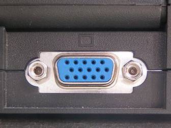
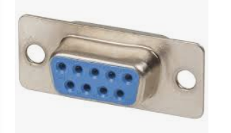
A DB9 connector has the same size shell but only two rows.
I bought mine at Jameco Electronics. They call it a “CONN,DSUB,15PIN FEM,BLUE .590"TIN LDS, RIGHT ANGLE” which is not a good description. They say the manufacturer’s part number is Shogyo International DB15-F-PCB. That’s a bad description too. But it is the right part. But while I was writing this I discovered that Jameco has discontinued it.
This is the part.
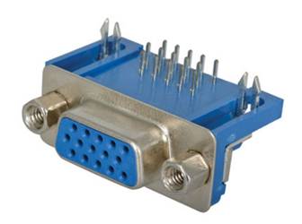
In finding another source I found that most companies wrongly call it a DB15 connector. In order to get the right part you search for “VGA Connector PCB” and then look very closely at the picture. I found some on Amazon, sold by uxcell. I got 10 for $8.72.
uxcell 10Pcs DB 15 Pin 3 Row Female D-SUB VGA Connector PCB Mounting Right Angle
You can find the part on eBay with costs and delivery times that vary widely.
I recommend you make sure you can get the connectors before you order boards.
2. The 75 Ohm parallel resistors might not be needed. It depends on whether you have both your VGA monitor and the game monitor connected together. Play with it to get the video levels that you need.
3. You will need a VGA cable to go from the Adapter Board to the display.
Bonus Board #1 - BattleZone Engine Sound (Coin-Op)
This board produces the BattleZone Engine sound using the same circuit I designed for BattleZone except the engine speed is controlled by a pot instead of a single bit.
What?
If you have played the original BattleZone you might not have noticed that the engine has only two speeds: Idle and Fast. That is because I had only one hardware bit to control the speed. I used an RC circuit to ramp the voltage up and down to a 555 timer.
In this one I used an actual pot. You can use a Trimpot at R20 or a Real Pot (not both). If you use a Real Pot you will have to connect it to the circuit with wires. (There are only three wires.) If you want you can control it with your own voltage (0 - +5V). Trimpot R17 sets the idle frequency.
To do the engine sound I used two counters with different cycle rates. One divides by 10, the other divides by 12. Then I add several of the bits together. As you increase the frequency the difference frequency increases. That is what why the throbbing sound gets faster with engine speed. For the original circuit click here. The engine sound is on PDF page 6 in the lower right. The two counters are ICs F4 and F5 (LS161).
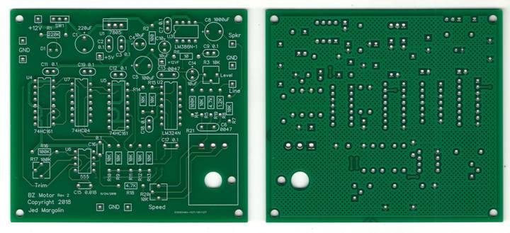
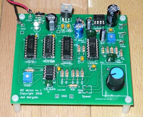
proj3_jm_bzmotor-R2.zip contains
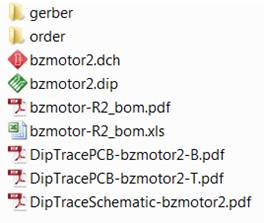
The zip file for ordering the board is in the folder: order > jm_bzr2.zip . The board dimensions are: 97.8mm x 87.7mm.
I could have done it with a microcontroller such as the Texas Instruments MSP430G2xxx series but then it would have just been a sound from a sound chip.
What can you do with the BattleZone motor other than to play with it for a few minutes?
1. Put it on a bicycle with a speed sensor. Add a speaker. The board has an LM386 speaker driver which is good for a few watts.
2. Put it in your electric car. Some time in the 1990s I was walking in a parking lot past a car that I realized was unusually quiet even though it had a gas engine. It was a bright sun-shiny day and if it had backed up I might not have noticed the backup lights. Now there are electric cars that are totally quiet. They (the government) could require electric cars to have a backup beeper but do you want your expensive electric car to sound like a garbage truck? How about a BattleZone tank instead, especially if you have a loud sound system with the bass turned up? You can use a speed sensor or control it manually. You can gun the engine when someone walks by. That works too when you are moving forward behind someone. You don’t have to use it all the time, just at slow speeds when pedestrians are around. Use it when you are driving slowly past an elementary school when the kids are out on the playground. That might be fun for everyone.
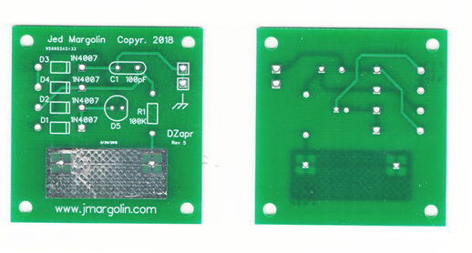
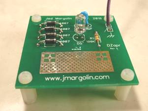
Bonus Board #2 - DeZapper
The DeZapper discharges the static electricity you get from walking on a carpet so it does not discharge through a USB Flash Memory that you are plugging into your computer. Flashes an LED.
The DeZapper discharges the static electricity you get from walking on carpet. https://en.wikipedia.org/wiki/Static_electricity
When you touch a doorknob you only get a zap. But when you insert a USB Flash Drive in a computer you zap the computer and can make it crash. (I hate it when that happens.)
To prevent this from happening you have to discharge yourself.
My desktop computers are insulated in the front and on the sides. The only exposed metal that is grounded is the exposed grounded chassis in the back.
You can attach a wire to the back, bring it out to the front, and touch the wire to discharge yourself. Even better would be to attach it to a small bare metal plate.
But I wanted to have some entertainment as well so I made the DeZapper where I discharge myself through an LED.
To install it, you attach a wire from one of the Ground terminals to the computer’s chassis ground in the back of the computer. At the end of the wire you can put a solder lug or an alligator clip. Or both.

With many computers there are four screws on the back of the computer that attach the case to the chassis. Remove one screw, put the solder lug on it, and put the screw back on.
If there are no screws, use the alligator clip on an exposed piece of metal on the computer.
Then put the DeZapper in a convenient location, like on your desk near your keyboard.
Use the Dezapper before you plug a USB Flash Drive into your desktop or anytime for some mild entertainment. To use the DeZapper just touch the exposed metal pad. Your static electricity will be discharged and the LED will flash. The brighter the flash the greater the charge you were carrying. It is more dramatic in a darkened room. Even more so if the room is completely dark (and you can still find the DeZapper.) With mine, in a very dark room, if I touch the DeZapper with one hand and wave my other hand somewhere around my head the LED will glow dimly. That is because we live in a soup of electromagnetic energy. In my case I am probably seeing the 60Hz Mains that is everywhere there is power. I can also put one hand on the DeZapper and the other on the metal swing lamp on my desk and have the LED glow dimly (in the dark). That does not mean my 2-wire lamp is suffering from unsafe leakage. It is because the DeZapper is so sensitive it will glow from just about any energy. The LED will glow with the DeZapper connected to 9V.
It also operates as an IQ Detector. The more intelligent you are, the brighter the flash. Ok, I made that part up.☺ The DeZapper just discharges your static electricity so you don’t zap your computer.
When you look at the schematic you will see that the LED is inside a diode bridge. That is because the static charge that you accumulate can be positive or negative depending on the carpet material and the material on the bottom of your shoes or slippers.
There is a series resistor that limits the current and extends the flash somewhat. I put in the capacitor because static discharges have a very fast rise time and I wanted to make sure the diodes have time to turn on. Use an ultra efficient LED. They are very cheap on eBay. You can use any color you like. I use white, it’s the color of lightning.
Here are the files. The board dimensions are 48.3mm x 49.6mm.
proj4_jm_zap-R5.zip contains:
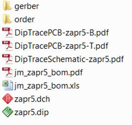
The zip file for ordering the board is in the folder: order > jm_zapr5.zip . The board dimensions are 48.3mm x 49.6mm.
Ordering boards
In my article on Making Things I list a Web site for finding board fabricators. https://pcbshopper.com/.
Then I list the three fabricators I have used. They have all made excellent boards for me.
JLCPCB: https://jlcpcb.com/quote
ALLPCB: http://www.allpcb.com/
PCBWAY: https://www.pcbway.com/
You upload the zip files:
jm_hdvgar2.zip
jm_hdvgad2r1.zip
jm_bzr2.zip
and/or
jm_zapr5.zip
The fastest and most reliable way to get boards is to use DHL shipping. They will deliver to your house. Do not use ePacket. They are unreliable and not worth the money you would save by using them.
Other Videos
I have posted videos of my other games (Star Wars and TomCat). I have also posted some GAL files that I found. I think they are for Hard Drivin’/Race Drivin’. Click here.
If you value what I have given you, you can show your appreciation by sending me $5.00 by PayPal. If you want to send me more, that would be ok too. To do this log into your PayPal account (www.paypal.com), find the Send button, and click on it. Then enter my email address (jm@jmargolin.com) and then the amount.
Thank you.
Jed
Copyright 2002, 2004, 2009, 2010, 2019 Jed Margolin