My Raspberry Pi Pico Projects Jed Margolin 10 July 2024
I have done many projects using the Texas Instruments MSP430G2xxx family of microcontrollers. This series was introduced in 1992 making it more than 32 years old. It isn’t known if Texas Instruments is planning to stop making them any time soon but they seem to be making fewer members of the family. This is their policy on obsoleting parts: https://www.ti.com/support-quality/quality-policies-procedures/product-change-notification.html . I do not find their policy very reassuring. In any event the MSP430G2xxx family is not very competitive with other microcontrollers. The reason I have still been using them is because they are available in DIPs. Their other microcontrollers, which are more capable and more reasonably priced, are not available in DIPs, only surface mount.
The Raspberry Pi Pico module is amazing. It is much faster than the MSP430G2xxx, has much more memory, has two cores, a 12-bit ADC, and is available with onboard WiFi and Bluetooth. The module comes in a 40-pin wide-DIP. As I write this in July 2024 the much less capable MSP430G2553IN20 has come down to $2.90 in ones from Digikey (it was more when I started using it) while the Raspberry Pi Pico module costs $4.00. The Raspberry Pi Pico W (the one with WiFi and Bluetooth) costs $6.00 . You can get the RPI Pico from Digikey as well as from places such as https://www.pishop.us/ . While the RPI Pico takes up more board space than the MSP430G2xxx it’s worth it for most of the things I do. I will be posting several of my Pico projects.
I probably spent at least 100 hours (most of it wasted) trying to get the Raspberry Pi Pico tools for Windows 10 to work so I can do my own software. None of the instructions online from various sources worked for me. Some guides tell you to use Powershell (or a Command Prompt) and do a bunch of typing. I suspect that those authors live in the Linux alternate universe. Other instructions probably worked until Microsoft “upgraded” Visual Studio 2019 to Visual Studio Code 2022. Supposedly the Linux tools are easier to get working if you have a Linux machine like the standard Raspberry Pi. When I started working on this in 2023 they weren’t making them that year.
I have more or less succeeded in getting the Windows tools to work.
I suggest that you get the software tools working before you spend money buying parts. Your pain threshold might not be as high as mine.
I am separately documenting how I am using the Raspberry Pi Pico tools. Click Here. Bear in mind that the Raspberry Pi Pico tools use software from several sources. One or more of the software toolmakers (especially Microsoft) could update their tools at any time and break everything. After all, this is Windows.
I made my first board with the Pico in order to monitor the pump in my well. My well stopped working in the middle of December 2022 right after the first real snow. Because of the snow and where the well is the well company couldn’t get their truck up to the well head to fix it until the snow melted and the ground dried up. That didn’t happen until the middle of May so I went 5 months without having running water in the house. On the bright side, because of all the snow I was able to go out every day and collect some snow and bring it into the house to melt. As a result I always had water to use in the toilet. (You fill the tank yourself.) I had gone through the same thing 8 years before that, only the well company was able to fix it in only 5 days. Both times the problem was that a hole had developed in the galvanized steel pipe in the well coming up from the pump. The pump started running more and more often until it destroyed itself.
This last time the well company used schedule 80 PVC instead of steel pipe. I don’t expect this problem to happen again but I don’t want to get caught by surprise again. That is why I made the pump monitor. I did a good job on it and have filed a patent application for it (a Provisional Application for a Patent). My pump monitor provides an early warning of many types of impending well failures and thereby reduces the constant anxiety that many well owners (like me) have that their well will stop working without warning. The EPA estimates that more than 23 million households rely on private wells for drinking water in the United States so I am probably not the only one with Well Anxiety. If I file a Non-Provisional Application and get a Patent I will post it.
In the meantime, The board I designed with the Pico has several other uses so I will post it along with software to use it.
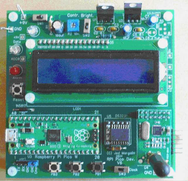
The board has:
1. A Raspberry Pi Pico (or Pico W);
2. A 1602 LCD using its 4-bit parallel interface. I am using the standard 5V part. The inputs work with 3.3V signals but because the outputs will be 5V I only write to it.
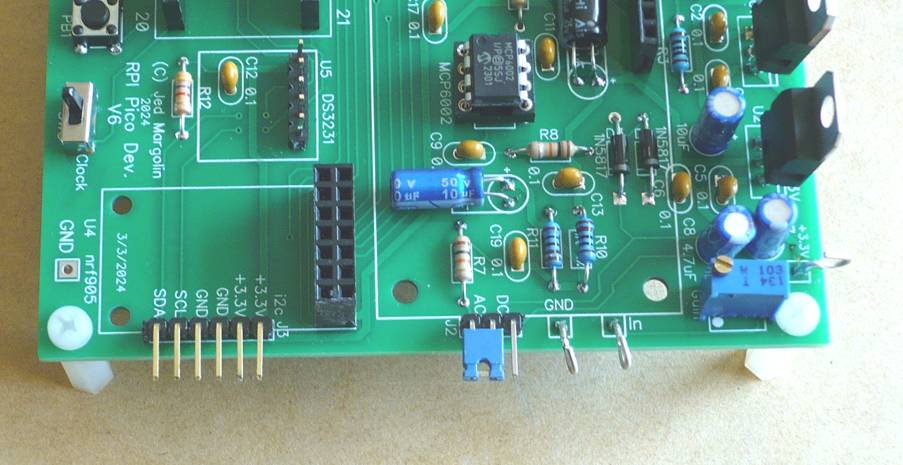
3. A DS3231 Real Time Clock (RTC). It uses the I2C interface.
4. An NRF905 RF Module. The NRF905 is a programmable transceiver by Nordic Semiconductor which can operate in the 433 MHz, 868 MHz, and 915 MHz bands and sends and receives data packets of up to 32 bytes in length. It can go a farther distance and operate through more walls than the WiFi or Bluetooth signals of the Raspberry Pi Pico W. It uses the SPI interface and several other bits. You program the frequency and an address so you can use many different channels in the same frequency band.
5. A preamp using an MCP6002 in the DIP package. This series of opamps is also available as a single opamp (MCP6001) but as a surface mount device only. In the event of a damaging signal overload a DIP in a socket is easier to replace than a surface mount device. There is an input trimpot that can be either a 3362P (1-turn) or a 3296W (25-turn). The input can be configured with a header pin jumper to be either 0V to 3.3V DC or 3.3Vp-p AC.
6. A slide switch and three pushbuttons. I use the switch to select either the primary program or the program to set the DS3231 RTC with the three pushbuttons. The three pushbutton switches are available for the primary program as well.
7. Two LEDs controlled by the Pico.
8. There is a header that brings out a UART port. I use a CH340 serial-to-USB adapter to connect the UART to a PC running a terminal program. The header also has a pin connected to a Pico input. I use a pin jumper to ground it to select one of two NRF905 channels.
9. There is also a header to bring out the I2C bus to use for other I2C devices. I use it for a BME-280 which is a sensor for temperature, humidity, and atmospheric pressure. I2C devices are addressable through the I2C protocol so the BME-280 and DS3231 coexist on the same bus.
The board runs from nominally +9V. The range of 8V to 12V is acceptable. Cheap switching power supplies are notoriously noisy (electrically). I had one that put out an enormous amount of hash on the Mains that interfered with another project connected to the same Mains circuit. You might consider a linear power supply if you can still find one.
For the schematic Click Here.
For the Parts List (Bill of Materials) Click Here.
For the zipped Gerber files Click Here.
The board is 3.90” x 3.90” = 99.1mm x 99.1mm. If you buy boards from China, if the boards are no larger than 100mm x 100mm they are really cheap. As I write this, it costs as little as $2 for five boards at www.jlcpcb.com. The major cost is shipping. Shipping is cheaper if you are willing to wait longer for delivery.
Another good company is www.pcbway.com. If you buy the boards from them using this link they will give me a small royalty that I can use to buy more boards from them. https://www.pcbway.com/project/shareproject/W56602ASD91_jm_rpi_pico_v6_ee5579df.html
Pcbway has a free online Gerber file viewer where you upload the zipped Gerber files at https://www.pcbway.com/project/OnlineGerberViewer.html
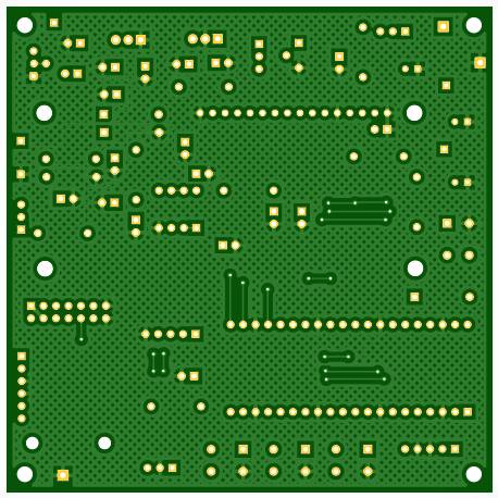
This is the bare board:
|
|
|

Here is a picture of the board with everything stuffed but without the Pico, LCD, DS3231, and NRF905 plugged in.
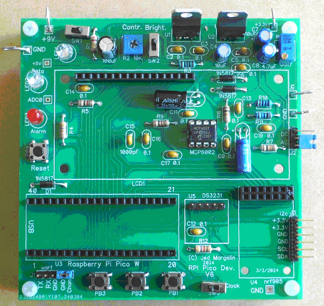
Note that two of the capacitors (C10 and C18) have to be mounted horizontally to provide clearance under the LCD.
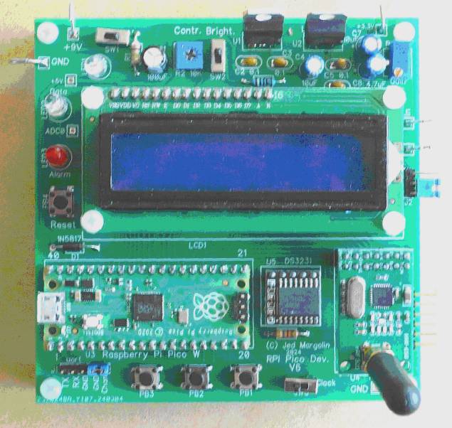
This is the board with everything mounted.
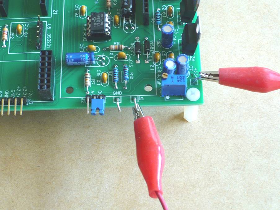
This is with the preamp input configured for a DC input ( 0 - 3.3V) and testing with a 3.3V input.
This is it configured for an AC input (3.3Vp-p).
If you are not going to use the ADC you can leave the preamp parts unstuffed.

With everything in this configuration mounted:
If you don’t have a lot of experience making things you should read my short version of Making Things. Click Here.
And a word about Chinese Picos.
You can get Chinese Picos on AliExpress.com cheaper than the official Picos (typically for less than $2.00). However:
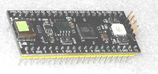
1. The official Pico has a row spacing of 0.7” (17.8mm). That is the spacing between the pins, not the width of the board. Some of the Chinese Picos have a row spacing of 0.6” instead of 0.7”.
2. The Chinese Picos use USB-C, not USB-A. That’s ok, all the new stuff is USB-C.
3. I bought four Chinese Picos from (I will call) Company A. The ADC did not work on any of them. Everything else on them seems to work, I have some projects that don’t use the ADC, and I paid $1.98 (each) for them. When the first one didn’t work I thought it was my code. Then I tried an official Pico and it worked just fine.
4. I tried again (later) with Company B, buying five. Again, the ADC did not work on any of them. Everything else seems to work, and I paid $2.02 for them.
5. Much later I bought five from Company C for $1.82 (each). The ADC worked fine on all of them.
6. The Chinese Picos are not as of this writing available with WiFi/Bluetooth. That’s ok, I haven’t figured out how to make WiFi/Bluetooth on the official Pico work (yet).
On the other hand:
1. The Chinese Picos have a Reset pushbutton on the module as well as the Boot pushbutton. You don’t have to unplug-and-replug the USB cable to get it into Boot Mode. This is useful because you can play with the Pico without needing my board (which has a Reset pushbutton on it).
2. The Chinese Picos use a linear voltage regulator to get +5V down to +3.3V. The official Pico uses a switching regulator which adds unavoidable noise to the ADC.
3. The Chinese Picos come with the headers. (You still have to solder them yourself). The Chinese Picos that I got all came with a right-angle 4-pin header for the development port. That won’t fit with my board. You have to use a straight 4-pin header.
4. The Chinese Picos come with at least 4MBytes of Flash and are available with even more. The official Pico comes with 2MBytes of flash. (My programs don’t come even close to needing 2MBytes.)
5. It comes with a WS2812 RGB LED that uses complicated timing to select Red, Green, or Blue and which can be daisy-chained. I guess it must be popular in China and they think it is popular here, too. Or maybe someone pranked them and told them that it is popular here.
As a result of my experience, I don’t think I would use Chinese Picos in a production unit and I would be careful about using one in developing a prototype for a production unit.
This is one of the Chinese Picos that I bought. I marked the top of the USB connector Green because the ADC works on this one.
The other parts I have gotten from AliExpress have been just fine (and inexpensive): LCD1602, DS3231, NRF905, BME-280, male and female header strips, resistors, capacitors, etc. You have to read the parts descriptions carefully. The companies tend to leave out information that you need to have complete confidence that it is the part you want.
Software
Note 1 - Most of my variables are global. I don’t want to waste time passing pointers to variables that are global anyway. (I do use pointers for some things, like structures and strings.) If you submit programs like mine for a class assignment you will probably get a bad grade because you are not supposed to do it this way.
Note 2 - The Pico compiler thinks integers are 32 bits so I am trying to use the C++ convention where the size is explicitly stated. I have not changed everything to this convention.
|
Name |
C++ |
Bytes |
Range |
|
bool |
|
1 |
true or false |
|
signed char |
int8_t |
1 |
-128 to 127 |
|
unsigned char |
uint8_t |
1 |
0 to 255 |
|
short int |
int16_t |
2 |
-32768 to 32767 |
|
unsigned short int |
uint16_t |
2 |
0 to 65535 |
|
int |
int32_t |
4 |
-2147483648 to 2147483647 |
|
unsigned int |
uint32_t |
4 |
0 to 4294967295 |
|
long int |
int32_t |
4 |
-2147483648 to 2147483647 |
|
unsigned long int |
uint32_t |
4 |
0 to 4294967295 |
|
long long |
int64_t |
8 |
-9,223,372,036,854,775,808 to 9,223,372,036,854,775,807 |
|
unsigned long long |
uint64_t |
8 |
0 to 18,446,744,073,709,551,615 |
|
float |
|
4 |
+/- 3.4e +/- 38 (~7 digits) |
|
double |
|
8 |
+/- 1.7e +/- 308 (~15 digits) |
|
long double |
|
8 |
+/- 1.7e +/- 308 (~15 digits) |
|
wchar_t |
|
2 or 4 |
1 wide character |
Note 3 - I use the uart with a CH340/CH341 USB to TTL Adaptor. This is not USB to Serial Port. Serial Port is RS-232 which was originally a +22V/-22V signal level and used a DB25 connector. Later the voltage level was dropped to as little as +5V/-5V and a DB9 connector could be used. The CH340 is not that. The CH340 does TTL levels but +3.3V is supported. There is a USB connector on one end and a 6-pin header on the other. Select 3V3 with the Header Plug.
|
5V |
Don’t Use |
|
VCC |
Header Plug |
|
3V3 |
Header Plug |
|
TXD |
To My RXD |
|
RXD |
To my TXD |
|
GND |
To My GND |
There are drivers for several operating systems: Windows 7, Windows 10, probably Windows 11, MAC, Linux. There does not appear to be drivers for Chromebook unless you make it a Linux machine. My Windows 10 PC already had the drivers for it. I use it with a freeware serial program called AccessPort from http://www.sudt.com/en/ap/index.html If you use the keyboard check the box that says Real Time Send.
A. jm_pico-lcd-rtc.zip For the .uf2 file Click Here. [Version 7/21/2024]
This uses the LCD, the ds3231 RTC, and the switches.
1. With SW1 closed it allows you to set the ds3231 time and date. (When SW1 is changed it is necessary to Reset the Pico with PB4.)
It starts with showing the time and date. Then you use the pushbuttons to set the time and date. PB3 advances to the next step in setting the time. PB1 increments the value. PB2 decrements the value.
2. With SW1 open it demonstrates the functions to write to the LCD with canned messages and with variables in different sizes and formats.
Hex: char (8-bits), int16, int32 All unsigned
Convert Hex to BCD: char (3 BCD), int16 (5 BCD), int32 (10 BCD), unsigned and signed.
3. There are also functions to send canned messages and variables out through the uart. You can time-stamp them using the ds3231 if you like.
B. jm_pico-adc-clock.zip For the .uf2 file Click Here. [Version 7/21/2024]
This tests the Pico’s ADC. You can also use it to develop your own ADC code for your own projects.
1. With SW1 closed it allows you to set the ds3231 time and date. (When SW1 is changed it is necessary to Reset the Pico with PB4.)
It starts with showing the time and date. Then you use the pushbuttons to set the time and date. PB3 advances to the next step in setting the time. PB1 increments the value. PB2 decrements the value.
2. With SW1 open it runs the ADC test program.
Although the Pico ADC is rated as 12-bits, it is noisy. The noise comes from two sources:
a. The RP2040 is a mixed-signal device which means it has both analog and digital circuits on the same chip. That makes it difficult to keep digital crap out of the analog part. (The MSP430G2553 has the same problem.)
b. The RP2040 runs at 3.3V. The USB port provides nominally 5V. When you run it from your own circuitry it is easiest to also run it from a 5V source. That is why the Pico has a 3.3V voltage regulator. Unfortunately, the official Pico uses a switching regulator so it also contributes noise. There is a mode that supposedly reduces the switching noise a little at the expense of increasing the current consumption a little. But face it, the Pico is not really suitable for operating from a battery.
My software also sends the ADC values out through the uart.
The program starts by reading 256 values at a time. It reports the highest value, lowest value, difference, and average. It does this every 4 seconds. It can also do this using the average of 32 values, 16 values, 8 values, and 4 values. It can also do this reading 1 value every second. You select which test by cycling through them. PB1 increments the selection of the test, PB2 decrements the selection of the test. The results are shown on the LCD and out through the uart.
C. jm_pico-flash.zip For the .uf2 file Click Here. [Version 7/21/2024]
Flash Memory - The Pico uses a separate Flash Memory for the program. The official Pico uses the Winbond W25Q16JV 3V 16M-Bit Serial Flash Memory with Dual/Quad SPI Interface. That is 2 MBytes = 2,097,152 bytes. You can use the Flash Memory that isn’t used for your program to store whatever you want. I sometimes use it to keep a time-stamped data log.
My explanation of how to use the Pico’s Flash Memory to log your own data is a little long so I am posting it separately. Click Here.
D. jm_pico-bme280.zip For the .uf2 file Click Here. [Version 7/25/2024]
This reads the Bosch BME-280 sensor which reads temperature, humidity, and absolute atmospheric pressure. It displays it on the LCD and can also keep a time-stamped log in Flash memory which can be retrieved through the uart. It also reports which part you have, a BME-280 or a BMP-280.
There is a difference between the BME-280 and the BMP-280. The Bosch BMP-280 reads the temperature and the absolute air pressure. The Bosch BME-280 reads the temperature, the absolute air pressure, and the humidity. Some of the times that I have bought a BME-280 on eBay the sellers have sent me the BMP-280. I have written about how to tell the difference. Click Here It includes a section on why Barometric Pressure and Absolute Air
Pressure are different when you are not at sea level and why it is important that you know that.
1. With SW1 closed it allows you to set the ds3231 time and date. (When SW1 is changed it is necessary to Reset the Pico with PB4.)
It starts with showing the time and date. Then you use the pushbuttons to set the time and date. PB3 advances to the next step in setting the time. PB1 increments the value. PB2 decrements the value.
2. With SW1 open it runs the BME-280 program.
E. Test the NRF905 RF Module in transmit mode. It sends 32-byte packets with test data that it also sends through the uart (in hex). Use it with the NRF905 RX Test program.
jm_pico-nrf905-tx.zip For the .uf2 file Click Here. [Version 7/8/2024]
F. Test the NRF905 RF Module in receive mode. It receives 32-byte packets that it sends through the uart (in hex). Use it with the NRF905 TX Test program.
jm_pico-nrf905-rx.zip For the .uf2 file Click Here. [Version 7/8/2024]
If you value what I am teaching you and giving you, you can show your appreciation by sending me $10 using PayPal. To do this log into your PayPal account (www.paypal.com), find the Send button, and click on it. Then enter my PayPal email address (jm@jmargolin.com) and then the amount.
Documentation:
A. Raspberry Pi Pico - https://www.raspberrypi.com/documentation/microcontrollers/raspberry-pi-pico.html
I am mirroring several of the documents.
1. Pinouts: For a local copy Click Here
2. RP2040 Datasheet: https://datasheets.raspberrypi.com/rp2040/rp2040-datasheet.pdf
For a local copy Click Here.
3. Getting Started with Raspberry Pi Pico (C/C++): https://datasheets.raspberrypi.com/pico/getting-started-with-pico.pdf
For a local copy Click Here.
4. Raspberry Pi Pico C/C++ SDK. https://datasheets.raspberrypi.com/pico/raspberry-pi-pico-c-sdk.pdf
For a local copy Click Here.
5 Windows Installer: https://www.raspberrypi.com/news/raspberry-pi-pico-windows-installer/
A one-click installer for the Pico C/C++ SDK for Windows 10 and Windows 11.
B. 1602 LCD: https://www.digikey.com/htmldatasheets/production/1542762/0/0/1/hd44780u-lcd-ii-.pdf
For a local copy Click Here.
C. DS3231 Real Time Clock: https://www.analog.com/media/en/technical-documentation/data-sheets/DS3231.pdf
For a local copy Click Here.
D. MCP6001 family: https://ww1.microchip.com/downloads/en/DeviceDoc/MCP6001-1R-1U-2-4-1-MHz-Low-Power-Op-Amp-DS20001733L.pdf
For a local copy Click Here.
E. NRF905 RF Module Documentation 1.5: https://infocenter.nordicsemi.com/pdf/nRF905_PS_v1.5.pdf
For a local copy Click Here.
F. Winbond W25Q16JV 3V 16M-Bit Serial Flash Memory with Dual/Quad SPI Interface
For a local copy Click Here.
.end