My Raspberry Pi Pico Projects - 2 Jed Margolin 18 January 2025
Several years ago I did a project called GPS Clock and Armageddon Alarm. This is an updated version.
A GPS Module using the U-blox NEO7M is used to receive the GPS timing signals to show the exact time on a 16x2 LCD display. In addition to the display, the end of each minute is signaled with a musical cord. To hear it Click Here.
It features an Armageddon Alarm Mode. I usually receive 11 or 12 GPS satellites. If the number of satellites drops to four or fewer something bad is happening. The odds that the GPS system is having a technical problem are vanishingly small.
What is happening is Armageddon.
Armageddon can happen in several ways:
a. A huge coronal mass ejection (CME) from the Sun that hits the Earth. The CME will burn out all of the satellites in orbit as well as the power grids (the Eastern Grid, the Western Grid, and the Texas Grid). In 1859 a huge CME (the Carrington Event) hit the Earth and burned out telegraph lines all over North America. See https://en.wikipedia.org/wiki/Carrington_Event . The reason it didn’t burn out anything else was because there wasn’t anything else, not even power lines. The telegraph offices ran on batteries.
b. A Global Thermonuclear War. The first thing everyone will do when they start Armageddon is destroy or otherwise disable everyone else’s satellite navigation systems.
The GPS Clock With Armageddon Alarm will give you instant notice by flashing the red LED and by playing this: Click Here. It also provides a 3.3V logic level signal that you can connect your own alarm to. (The interface depends on what your alarm is so you will have to do that yourself.)
You don’t have to be a Prepper to want to know when the World is Ending.
After I designed this project (and first posted it), from GPS World November 29, 2021:
The Kremlin warned it could blow up 32 GPS satellites with its new anti-satellite technology, ASAT, which it tested Nov. 15 on a retired Soviet Tselina-D satellite, according to numerous news reports.
Russia then claimed on state television that its new ASAT missiles could obliterate NATO satellites and “blind all their missiles, planes and ships, not to mention the ground forces,” said Russian Channel One TV host Dmitry Kiselyov, rendering the West’s GPS-guided missiles useless. “It means that if NATO crosses our red line, it risks losing all 32 of its GPS satellites at once.”
Since my original project in 2021 the World situation has become much more precarious.
I have also realized that there is one more thing that might cause you to lose GPS reception. An extraterrestrial ship can be hovering over your house getting ready to abduct you. This alarm might alert you so you can greet the ETs wide awake and with a taser. I recommend a taser instead of a firearm because you might not be exactly wide awake and you do not want to put holes in your house (or a loved one) unnecessarily.
The original GPS Clock and Armageddon Alarm used an MSP430G2553 for the GPS stuff and an MSP430G2402 for the PWM sounds. This updated version uses a Raspberry Pi Pico. The Pico is faster, has more memory, and has 2 cores. I use one core for the GPS stuff and the other core for the PWM sounds. Last year I started using the Raspberry Pi Pico instead of the Texas Instruments MSP430G2xxx family of microcontrollers. I posted several projects. Click Here. If you have not used the Pico I recommend you read it for background because I tell the story of how I got the Pico SDK installed and how I use it. I say that:
I suggest that you get the software tools working before you spend money buying parts. Your pain threshold might not be as high as mine.
and
I am separately documenting how I am using the Raspberry Pi Pico tools. Click Here. Bear in mind that the Raspberry Pi Pico tools use software from several sources. One or more of the software toolmakers (especially Microsoft) could update their tools at any time and break everything. After all, this is Windows.
Those statements are still true. The original article also contains other useful information. You should at least read this short piece on making things: Click Here.
I have done a new board for the Raspberry Pi Pico. It has:
Raspberry Pi Pico
16 x 2 LCD
Blue 4-pin NEO7M GPS Module
3 pushbutton switches
1 slide switch
1 Green User LED
1 Red User LED
Header for UART
Header for I2C interface
Output Filter using MSP6002 for making Pulse Width Modulation (PWM) sounds
It can be powered by either a 9V DC supply or by the USB port on the Pico, you make the decision when you stuff the board.
Provision for using a backup battery for the NEO7M
This last part about “Provision for using a backup battery for the NEO7M“ requires some explanation. Although the NEO7M boards that I have gotten from China (www.aliexpress.com) all came with an EEPROM (a 24C32 type) the NEO7M doesn’t use it. The NEO7M still has the DDC (I2C) interface but it doesn’t use it for backup. From the NEO7M Datasheet:
1.11.4 Display Data Channel (DDC)
An I2C compliant DDC interface is available for communication with an external host CPU or u-blox Wireless modules. The interface can be operated in slave mode only. The DDC protocol and electrical interface are fully compatible with Fast-Mode of the I2C industry standard. Since the maximum SCL clock frequency is 400 kHz, the maximum transfer rate is 400 kb/s.
See NEO-7 Data Sheet (UBX-13003830 - R04) PDF page 11. Click Here.
It doesn’t say anything about EEPROMs. I have verified that the NEO7M doesn’t use the EEPROM by putting an oscilloscope probe on the EEPROM’s SCL and SDA pins. There are no signals there at any time. The NEO6M does seem to support the EEPROM, there are signals there. But the NEO7M, no. Apparently, the Chinese companies that make the NEO7M modules are using the boards they use for the NEO6M modules and are putting the EEPROM on it because they don’t know it isn’t being used.
This is from the Neo6 Datasheet (GPS.G6-HW-09005-E) PDF page 11 (Click Here):
1.12.4 Display Data Channel (DDC)
The I2C compatible DDC interface can be used either to access external devices with a serial interface EEPROM or to interface with a host CPU. It is capable of master and slave operation. The DDC interface is I2C Standard Mode compliant. For timing parameters consult the I2C standard. The DDC Interface supports serial communication with u-blox wireless modules. See the specification of the applicable wireless module to confirm compatibility. The maximum bandwidth is 100kbit/s.
1.12.4.1 External serial EEPROM
NEO-6 modules allow an optional external serial EEPROM to be connected to the DDC interface. This can be used to store Configurations permanently.
For more information see the LEA-6/NEO-6/MAX-6 Hardware Integration Manual [1].
Use caution when implementing since forward compatibility is not guaranteed.
u-blox kept their promise.
The only way to provide a backup for the NEO7M is in its internal RAM. This requires that it has power at all times. (It uses a separate pin for this.)
The Chinese manufacturers do not use a Lithium Ion battery (like a CR2032). Exporting Lithium Ion batteries from China is a complicated procedure and can take 2 months. See: https://deefreight.com/how-to-ship-lithium-batteries-from-china-safely/ and https://cargofromchina.com/sea-freight/
All of the NEO7M modules that I have bought from China use a super capacitor but they are not very super. One lasted 30 minutes. Another lasted 30 seconds.
My board allows you to use your own backup battery. I use a CR2032 in a battery holder with wire leads. It also has its own On-Off switch. You could use 2 AAA batteries in series. My board has a 1N5817 Schottky diode to prevent the NEO7M from trying to charge the battery. (You are not supposed to recharge non-rechargeable batteries.)
This is why you want to use it. Without it the NEO7M has to do a cold start every time it powers up. Part of the startup requires you get the current number of Leap Seconds in order to get the correct time. For various reasons the GPS system does not use the current Leap Second. It does send the current Leap Second but since the number of Leap Seconds does not change very often the GPS system only transmits it every 12.5 minutes. You can read about GPS Leap Seconds here: https://www.cnmoc.usff.navy.mil/Our-Commands/United-States-Naval-Observatory/Precise-Time-Department/Global-Positioning-System/USNO-GPS-Time-Transfer/Leap-Seconds/ and here: https://gpsd.gitlab.io/gpsd/NMEA.html#_talker_ids
When you do a cold start the NEOx-M uses a default value for Leap Seconds. The value it uses depends on what it was when the NEO was manufactured since the NEOs that end in “M” use masked ROM and cannot be updated. You can read about what the Leap Second was in the past here: https://en.wikipedia.org/wiki/Leap_second
Note that using your own backup battery requires that you solder a wire to the super capacitor. Fortunately, you solder it to the super capacitor’s top bracket and the bracket is easily solderable.
If the Chinese manufacturers took off the EEPROM and the super capacitor (which probably isn’t free either) they would have more than enough room to put on 2 x LR44 alkaline batteries. There is no problem exporting alkaline batteries from China.
There is another reason for using a real backup battery. By default the NEO7M sends lots of NMEA messages. (To read about NMEA messages and the propriety messages produced by the NEO7M Click Here.) I don’t need (or want) all of them and there are some that I want that are not sent by default. You can use u-blox’s u-center program (https://www.u-blox.com/en/product/u-center) to set it up but without backup power you will lose what you have set up.
The way I have dealt with this particular problem is that my programs turn off all of the NEO7M messages and then turn on the ones I want. u-blox does not do a good job documenting how to do this so I used u-center with a second ch340 to capture the data stream as I first turned off all the messages at once and then, one at a time, turned on the ones I want. This code is in my programs.
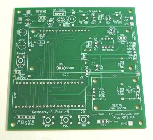
Bare Board Top
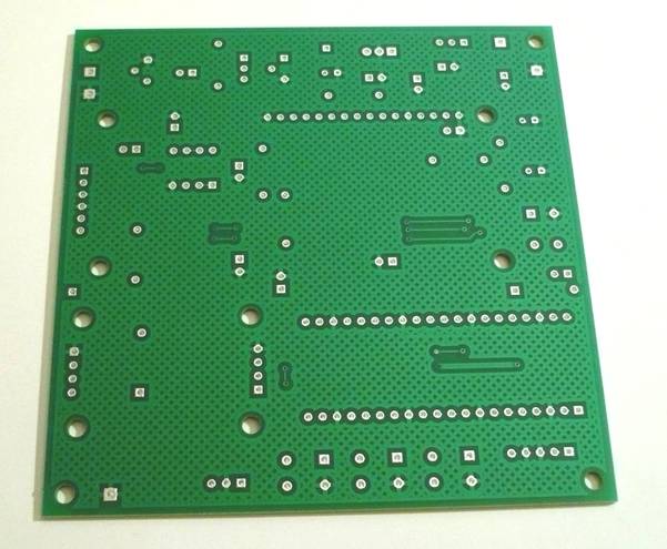
Bare Board Bottom
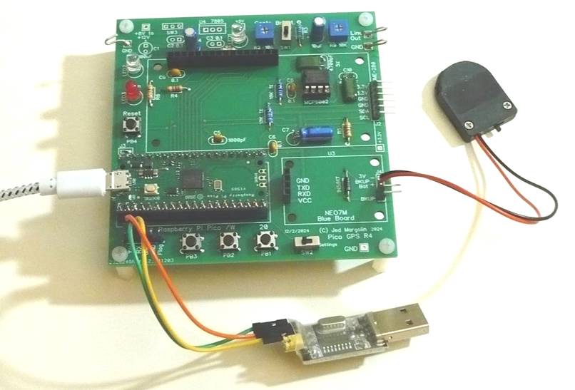
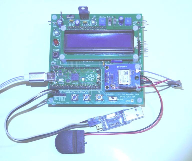
The board can be setup to use either USB power or a 9VDC power supply. Here is a picture of the board setup for USB power. It shows the Pico but without the LCD and NEO7M plugged in. Note that three of the capacitors (C7, C10 and C11) have to be mounted horizontally to provide clearance under the LCD. I have left room to do that. For this project I used the ch340 only for debugging. It is not needed for normal use.
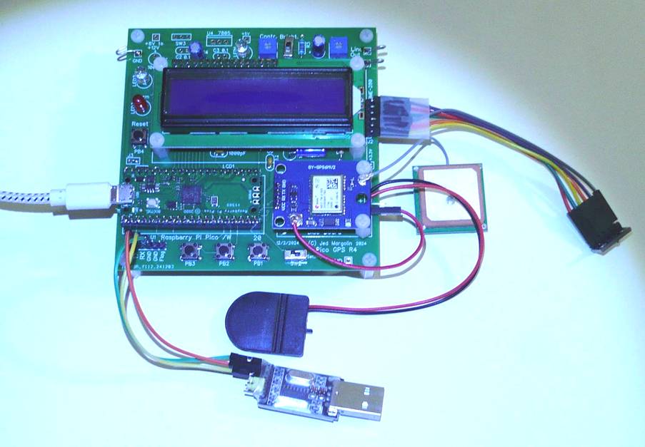
Board stuffed and ready to go
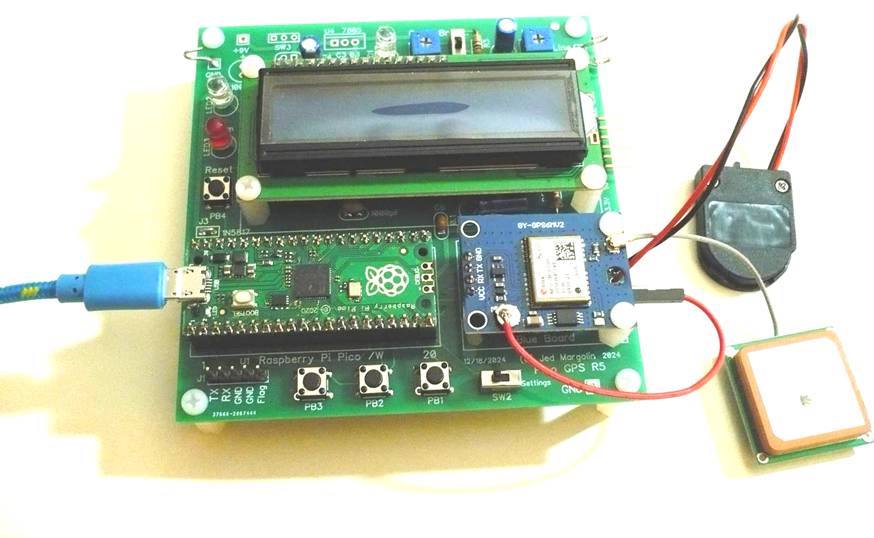
This one is stuffed for 9VDC power. In this one I am using the small rectangular GPS antenna. It works just as well as the large square antenna.
This one uses USB power and has a BME-280 sensor connected to the I2C interface for the GPS Altitude project.
Now that I have used them in both configurations (USB power and 9VDC power) I think I prefer USB power. USB power supplies cost less and seem to be more reliable than 9VDC switching power supplies.
Note that the audio output needs an amplified speaker. A cheap bluetooth speaker with an aux input should be just fine.
Also note that the Official Pico uses a Micro USB-A connector while most Chinese Picos use USB-C.
For the schematic Click Here.
For the Parts List (Bill of Materials) Click Here.
For the zipped Gerber files Click Here.
The board is 3.90” x 3.90” = 99.1mm x 99.1mm. If you buy boards from China, if the boards are no larger than 100mm x 100mm they are really cheap.
A good company is www.pcbway.com. If you buy the boards from them using this link they will give me a small royalty that I can use to buy more boards from them. https://www.pcbway.com/project/shareproject/GPS_Clock_and_Armageddon_Alarm_2_and_GPS_Altimeter_32a0b18f.html
Pcbway has a free online Gerber file viewer where you upload the zipped Gerber files at https://www.pcbway.com/project/OnlineGerberViewer.html
Other good companies are www.jlcpcb.com, www.nextpcb.com, and www.elecrow.com .
If you don’t have a lot of experience making things you should read my short version of Making Things. Click Here.
Software
Note 1 - Most of my variables are global. I don’t want to waste time passing pointers to variables that are global anyway. (I do use pointers for some things, like structures and strings.) If you submit programs like mine for a class assignment you will probably get a bad grade because you are not supposed to do it this way.
Note 2 - The Pico compiler thinks integers are 32 bits so I am trying to use the C++ convention where the size is explicitly stated. I have not changed everything to this convention.
|
Name |
C++ |
Bytes |
Range |
|
bool |
|
1 |
true or false |
|
signed char |
int8_t |
1 |
-128 to 127 |
|
unsigned char |
uint8_t |
1 |
0 to 255 |
|
short int |
int16_t |
2 |
-32768 to 32767 |
|
unsigned short int |
uint16_t |
2 |
0 to 65535 |
|
int |
int32_t |
4 |
-2147483648 to 2147483647 |
|
unsigned int |
uint32_t |
4 |
0 to 4294967295 |
|
long int |
int32_t |
4 |
-2147483648 to 2147483647 |
|
unsigned long int |
uint32_t |
4 |
0 to 4294967295 |
|
long long |
int64_t |
8 |
-9,223,372,036,854,775,808 to 9,223,372,036,854,775,807 |
|
unsigned long long |
uint64_t |
8 |
0 to 18,446,744,073,709,551,615 |
|
float |
|
4 |
+/- 3.4e +/- 38 (~7 digits) |
|
double |
|
8 |
+/- 1.7e +/- 308 (~15 digits) |
|
long double |
|
8 |
+/- 1.7e +/- 308 (~15 digits) |
|
wchar_t |
|
2 or 4 |
1 wide character |
Note 3 - I use the uart with a CH340/CH341 USB to TTL Adaptor. This is not “USB to Serial Port”. Serial Port is RS-232 which was originally a +22V/-22V signal level and used a DB25 connector. Later the voltage level was dropped to as little as +5V/-5V and a DB9 connector could be used. The CH340 is not that. The CH340 does TTL levels but +3.3V is supported. There is a USB connector on one end and a 6-pin header on the other. Select 3V3 with the Header Plug.
|
5V |
Don’t Use |
|
VCC |
Header Plug |
|
3V3 |
Header Plug |
|
TXD |
To My RXD |
|
RXD |
To my TXD |
|
GND |
To My GND |
There are drivers for several operating systems: Windows 7, Windows 10, probably Windows 11, MAC, Linux. There does not appear to be drivers for Chromebook unless you make it a Linux machine. My Windows 10 PC already had the drivers for it. I use it with a freeware serial program called AccessPort from http://www.sudt.com/en/ap/index.html If you use the keyboard check the box that says Real Time Send.
A. GPS Clock and Armageddon Alarm
Software: jm_pico-gps-clock.zip For the .uf2 file Click Here. [Version 1/16/2025]
1. With SW1 closed it allows you to set various things like the local offset from UTC, whether DST is observed, 12 hour mode, etc. (When SW1 is changed it is necessary to Reset the Pico with PB4.) It starts with showing the time and date. Then you use the pushbuttons to set the time and date. PB3 advances to the next step in the settings. PB1 increments the value. PB2 decrements the value. You can save the new settings in User Flash memory.
Converting UTC to Local Time is not as easy as you might think. When you subject hours (Pacific Time is UTC - 8 hours):
a. You might have to rollback the day;
b. When you rollback the day you might have to rollback the month;
c. When you rollback the month you have to know how many days are in the previous month. If you are rolling back March to February is it a leap year?
d. When you rollback January to December you have to rollback the year.
e. If you observe DST you have to know when the DST start and end dates are for the year and are you in the DST window?
If your UTC offset is positive there are similar problems but in reverse.
2. With SW1 open it does the GPS Clock and Armageddon Alarm.
There are diagnostic functions that are documented in the source code files.
B. GPS and Pressure Altitude
Software: gps_pressure.zip For the .uf2 file Click Here. [Version 1/16/2025]
I live in the mountains outside of Reno, Nevada. I have always been interested in the altitude of my house. According to the GPS App on my phone it would frequently read about 6,000 feet plus or minus a few feet but sometimes it would say 100 or 200 feet lower. Hmm.
Since I already had my own GPS Module (the NEO6M) and had written the software for it (for my GPS Clock) and I already had the BME-280 and had written the software for it I decided to do my own barometric altimeter which uses the air pressure to determine the altitude. It has turned out to be a lot more complicated than I thought.
First, why does the National Weather Service (NWS) and all the radio and TV stations report the Barometric Pressure at sea level even if your community is at an altitude of 4,500 feet? At sea level the standard air pressure on a nice day with the temperature of 15 deg C (59 deg F) is 29.92 inches of Mercury (1013.25 mb). In Reno, at an average altitude of 4,500 feet AMSL (Above Mean Sea Level), the standard air pressure is 859 mb (See https://www.mide.com/air-pressure-at-altitude-calculator). This means that the oxygen level at 4,500 feet is about 85% of what it is at sea level. At an altitude of 6,000 feet AMSL the air pressure is about 812 mb for an oxygen level of about 80% of what it is at sea level.
This has implications for more than just your lungs. It affects all internal combustion engines. With less oxygen they will produce less power unless they have a supercharger or turbocharger. And if they use a carburetor they will run rich. That is because carburetors dole out a measured amount of gas. With less oxygen they run rich. If you have a generator it will produce less than its rated power so you need to take that into account if you are sizing a generator.
It also affects the BTU rating of gas furnaces. And although “high altitude” orifices are available for gas furnaces there is usually only one. As a result gas furnaces will not be using the proper gas/air mixture and will probably run rich, thereby producing more pollution. A properly burning flame on a gas appliance should be blue in color with a tiny tip of yellow. If you wonder why candle flames are mostly yellow it is because the air must diffuse into the gas (the vaporized wax) as opposed to furnaces where the fuel/air is premixed before it is burned. Diffused flames cannot have a properly mixed fuel/air mixture. For proper efficiency you need a premixed flame. Gas furnaces should have a continuously variable control so the fuel/air mixture can be properly adjusted for altitude.
So, why does the National Weather Service (NWS) report the Barometric Pressure at sea level?
1. It might be because of why the NWS was established. From https://www.pbs.org/wgbh/americanexperience/features/hurricane-brief-history/
After a series of weather related disasters sank hundreds of boats on the Great Lakes, President Ulysses S. Grant ordered the army to systematically compile weather observations from stations across the nation. On November 1, 1870, weather forecasts for the eastern United States were being issued for the first time, although these were just 24 hours ahead. Within a few years, the system was expanded to include observations in the Caribbean, thus allowing forecasters to track storms in the Atlantic before they hit the coast.
It was about the weather at sea level. See also https://www.weather.gov/mob/history
2. Most of the U.S. population probably lives at or near sea level. Several years ago I contacted the U.S. Census Bureau to find out what percentages of the population lives at various altitudes. They said they didn’t have that information. That’s too bad. I think it would provide valuable epidemiological information for human health and safety. Does living at high altitude make it more likely that you will suffer from various medical problems (other than lung problems, of course). Is there any health benefit from living at high altitude? If you live at a higher altitude a healthy person will adapt by producing more red blood cells. Is there a benefit to that other than for breathing?
But someone has come up with a nice list: https://en.wikipedia.org/wiki/List_of_highest_communities_in_the_United_States
3. I read that all of the computer programs to predict the weather require the altitude at sea level even though altitude obviously affect the weather.
Another major user of atmospheric pressure is aviation.
Altitude from air pressure
There is a discussion at: https://physics.stackexchange.com/questions/333475/how-to-calculate-altitude-from-current-temperature-and-pressure
I am using an approximation of the Barometric Formula (https://en.wikipedia.org/wiki/Barometric_formula) which is a good approximation for altitudes below 9000 meters (about 30,000 feet) and when the temperature at sea level is 15 deg C (59 degrees F). The U.S. Weather Service does not report the temperature at sea level when they report the barometric pressure so it must be the standard 15 deg C. Besides, unless you live on a coast where would you measure the temperature?
The equation assumes a standard lapse rate. The lapse rate is more complicated than you might think: https://en.wikipedia.org/wiki/Lapse_rate and it appears that global warming is affecting the lapse rate.
Here is the formula most commonly used to calculate the Pressure Altitude from the air pressure:
H = 44330 * [1 - Pa/P0 ^ (0.190295)]
Pa = air pressure at altitude
P0 = air pressure at sea level (barometer)
H = pressure altitude in meters
Height Above Mean Sea Level (AMSL) is not an exact science. However, it is very useful when comparing altitudes. That is why airports report their altitude (however it is they determine what it is) and the current barometric pressure at the airport. As long as all of the aircraft pilots in the vicinity use the same values and the same methods they know where they are vertically in relation to everyone else.
The Barometric Altimeter was invented in the 1920s by Paul Kollsman. https://appel.nasa.gov/2010/02/27/ao_2-1_f_kollsman-html/
Kollsman was one of the great inventors of the 20th Century. I don't think he gets the recognition that he deserves.
How did Kollsman's altimeter work? It was purely mechanical. See https://www.aopa.org/news-and-media/all-news/2019/july/flight-training-magazine/how-it-works-altimeter
And you may find this video useful: https://www.youtube.com/watch?v=glcgxoGLHrQ
There is a difference between Pressure Altitude and Density Altitude. Air pressure is not affected by temperature so Pressure Altitude is not affected by the air temperature. Otherwise, if you flew into a mass of hot air you would think you are flying higher than you are and you could hit terrain. Density Altitude is affected by the temperature because the temperature does affect the air density and air density affects the aerodynamics of everything: the lift that the wings produce, the thrust of propellers, etc. It also affects the power that engines produce. Pressure Altitude is a way of telling pilots how their aircraft will handle.
GPS altitude is derived by GPS receivers using triangulation of several satellites to determine the distance to the satellites and then subtracting the altitude (for your coordinates) that comes from a mathematical model of the Earth as an oblate spheroid. The Earth is not a perfect spheroid so that GPS altitude cannot be relied on to be accurate.
GPS altitude is less accurate than the Pressure Altitude, sometimes much less accurate. This project allows you to compare them.
My device uses the NEO7M for time, coordinates, and GPS altitude. It uses the BME-280 for temperature, humidity, and air pressure. These things are displayed on the LCD. You can also specify that that they be recorded in a time stamped log in the Pico’s flash memory. Retrieving the log requires that you use the uart. I use the ch340 with the freeware serial program called AccessPort from http://www.sudt.com/en/ap/index.html.
You use it in this mode from the keyboard. The commands are:
V: Show Version
B: Show BME-280
O: Log BME-280 Once
L: Log BME-280 Every 5 minutes
X: Stop Logging BME-280
D: Dump All of the Flash Logs to uart
E: Erase Data Flash? (then Y/N)
S: Reset Start Date? (then Y/N)
P: BME-280 Parameters
R: Reset Barometric Reference to 29.92
F: Set Default Local Offset and DST
H: Repeat This List
Starting the program with SW1 in “Settings” mode allows you to set the Barometric Reference, the Local Offset Hours from UTC, and whether to observe DST. You use it with the LCD and the three pushbutton switches on the board.
Warning: Do not use this project for piloting an aircraft. For that you need to use an FAA certified Barometric Altimeter.
(I hope I didn’t need to tell you that.)
C. User Flash Memory Erase
Software: gps_erase.zip For the .uf2 file Click Here. [Version 1/16/2025]
If the flash memory that I use gets confused and you need to just erase it I have written a program for that. It uses the uart with the following keyboard commands:
V: Show Version
D: Dump All of the Flash Logs to uart
1: Erase Data Flash
2: Erase Start Date Flash
3: Erase Barometric Reference Flash
4: Erase Local Offset Flash
5: Erase DST Dates Flash
H: Repeat This List
If you value what I am teaching you and giving you, you can show your appreciation by sending me $10 using PayPal. To do this log into your PayPal account (www.paypal.com), find the Send button, and click on it. Then enter my PayPal email address (jm@jmargolin.com) and then the amount.
Documentation:
A. Raspberry Pi Pico - https://www.raspberrypi.com/documentation/microcontrollers/raspberry-pi-pico.html
I am mirroring several of the documents.
1. Pinouts: For a local copy Click Here
2. RP2040 Datasheet: https://datasheets.raspberrypi.com/rp2040/rp2040-datasheet.pdf
For a local copy Click Here.
3. Getting Started with Raspberry Pi Pico (C/C++): https://datasheets.raspberrypi.com/pico/getting-started-with-pico.pdf
For a local copy Click Here.
4. Raspberry Pi Pico C/C++ SDK. https://datasheets.raspberrypi.com/pico/raspberry-pi-pico-c-sdk.pdf
For a local copy Click Here.
5 Windows Installer: https://www.raspberrypi.com/news/raspberry-pi-pico-windows-installer/
A one-click installer for the Pico C/C++ SDK for Windows 10 and Windows 11.
B. 1602 LCD: https://www.digikey.com/htmldatasheets/production/1542762/0/0/1/hd44780u-lcd-ii-.pdf
For a local copy Click Here.
C. MCP6001 family: https://ww1.microchip.com/downloads/en/DeviceDoc/MCP6001-1R-1U-2-4-1-MHz-Low-Power-Op-Amp-DS20001733L.pdf
For a local copy Click Here.
D. Winbond W25Q16JV 3V 16M-Bit Serial Flash Memory with Dual/Quad SPI Interface
For a local copy Click Here.
E. NEO7M Datasheet. Click Here.
F. NEO7M Receiver Description Including Protocol Specification V14. Click Here.
.end